SALTSCAPES
Investigating salt as a building material
2023 | Academic | Independent project 2024–present | Personal project
AWARDS Future Icons ND Selects Award, July 2025
MATERIAL ARCHIVE Sea salt composite sample, Heatherwick Studio
EXHIBITIONS Future Icons Selects, London Craft Week, 83 Rivington Street, London, UK, May 2026 Material Matters, Space House, London, UK, September 2025 Future Icons ND Selects, New Designers, Business Design Centre, London, UK, July 2025 New Designers, Business Design Centre, London, UK, July 2024 Back of House, Cromwell Place Gallery, London Design Festival, London, UK, September 2023
One method is emergent and self-growing, the other engineered and mold driven. Together they frame salt as an active, scalable material system with structural strength and versatility. The work questions assumptions about permanence, value, and what constitutes a resource.
PUBLICATIONS | FEATURES “From salt to avocado waste: how far can material experimentation go?”, DesignWanted “Material Matters 2025: Seven Sustainable Highlights in London”, Archipanic, September 2025 “Seven Top Design Trends For 2025”, The Times UK, September 2025 “The 25 Best Shows At London Design Festival This Year”, The Times UK, September 2025 “Top Spots at New Designers”, Material Source, July 2024 “LDF 2023: Smile’s Material Highlights”, Smile Plastics, September 2023
ROLE Concept Development, Material Research, Formulation Testing, Digital Fabrication, Prototyping, Product Development
COLLABORATOR Ian Gm | Computational design
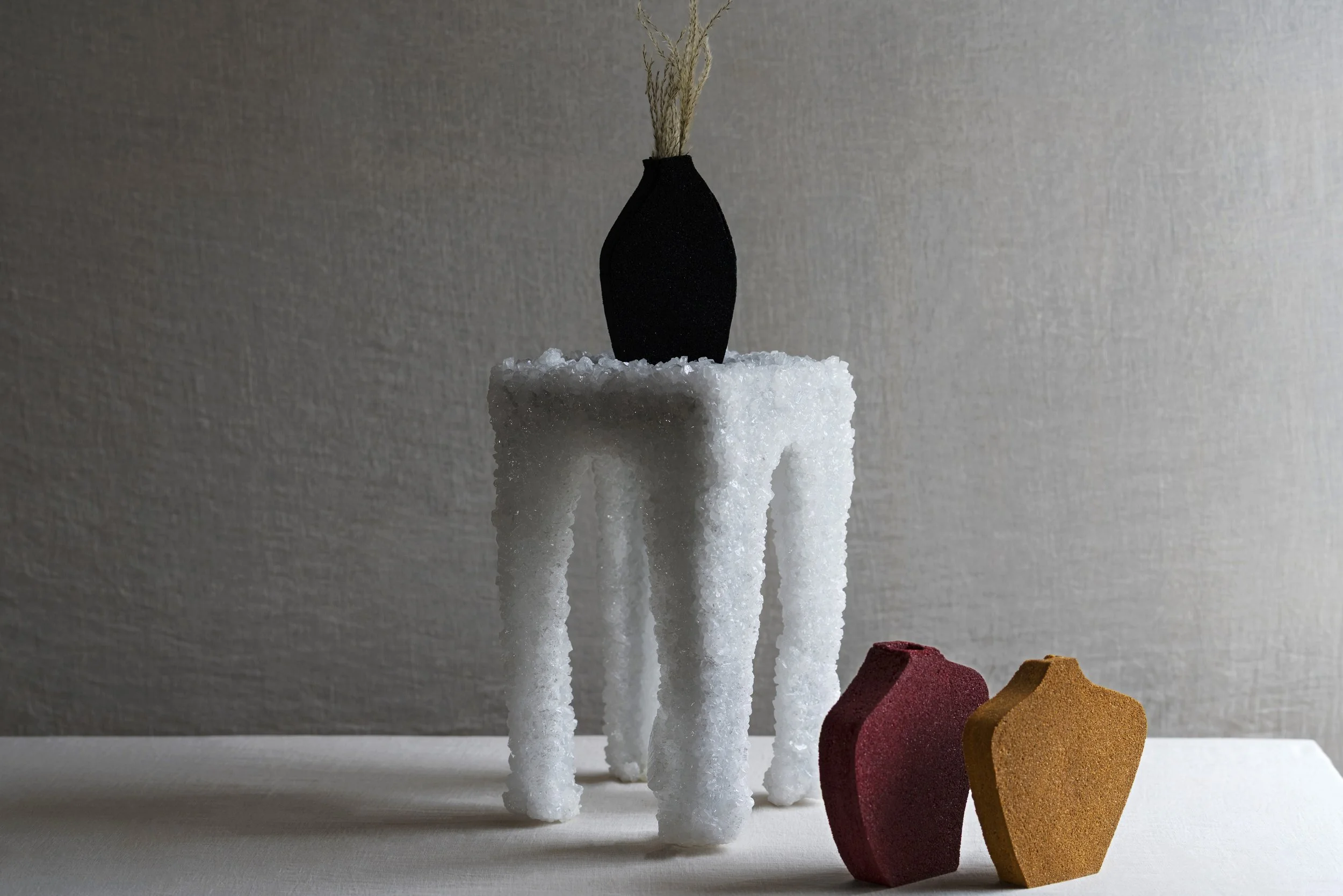
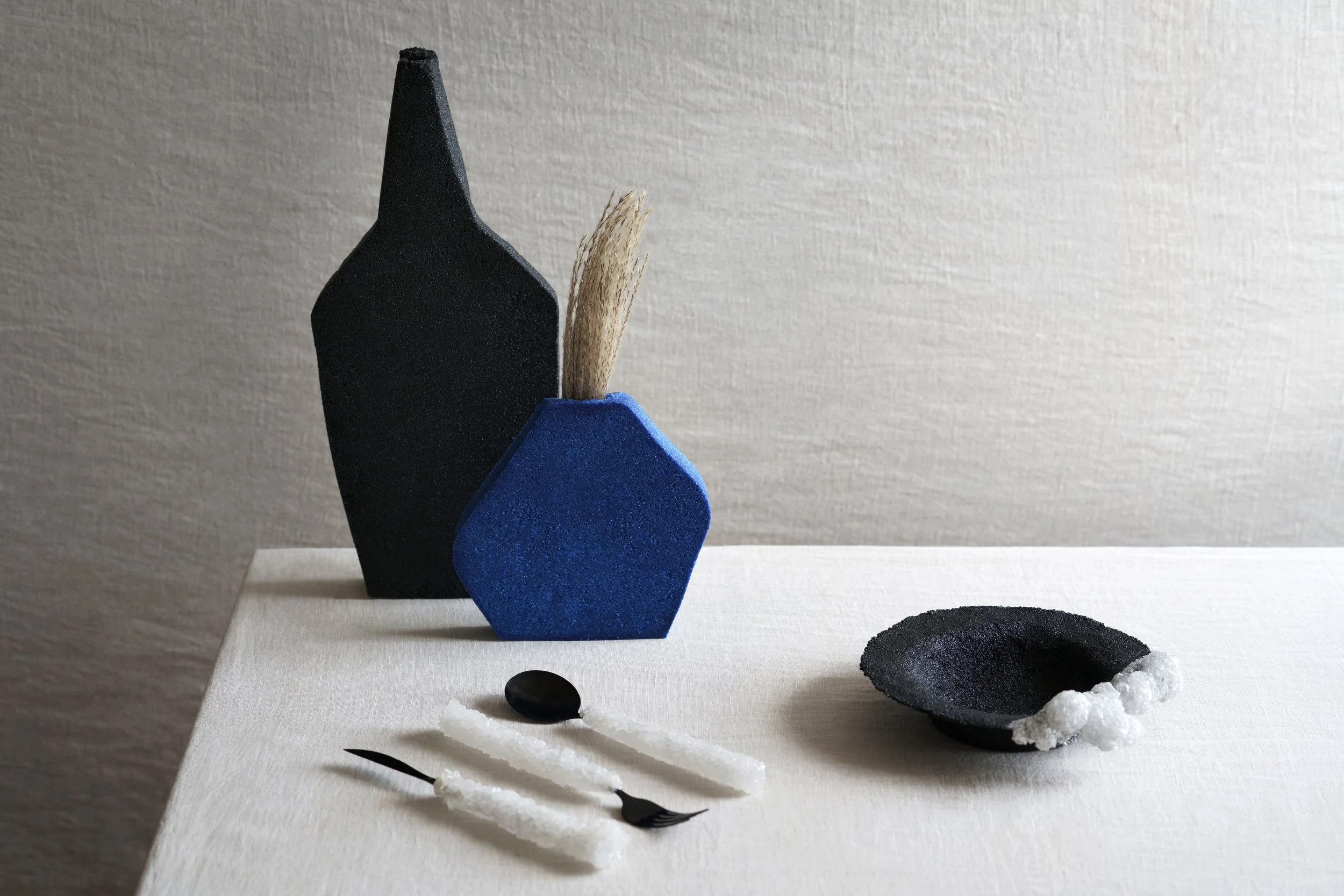
Saltscapes is a collection of furniture and homeware made from salt. In response to resource scarcity and environmental strain, the series explores how this abundant yet overlooked material could be applied to design and architecture. Through crystallization and composite fabrication methods, the work examines salt's physical, mechanical, and aesthetic properties, suggesting new possibilities for its use. Two complementary fabrication modes structure the research: crystallization, where salt accumulates on structural frameworks over time, and composites, where salt is bound and cast into stable forms.
Photography by Julia Brière
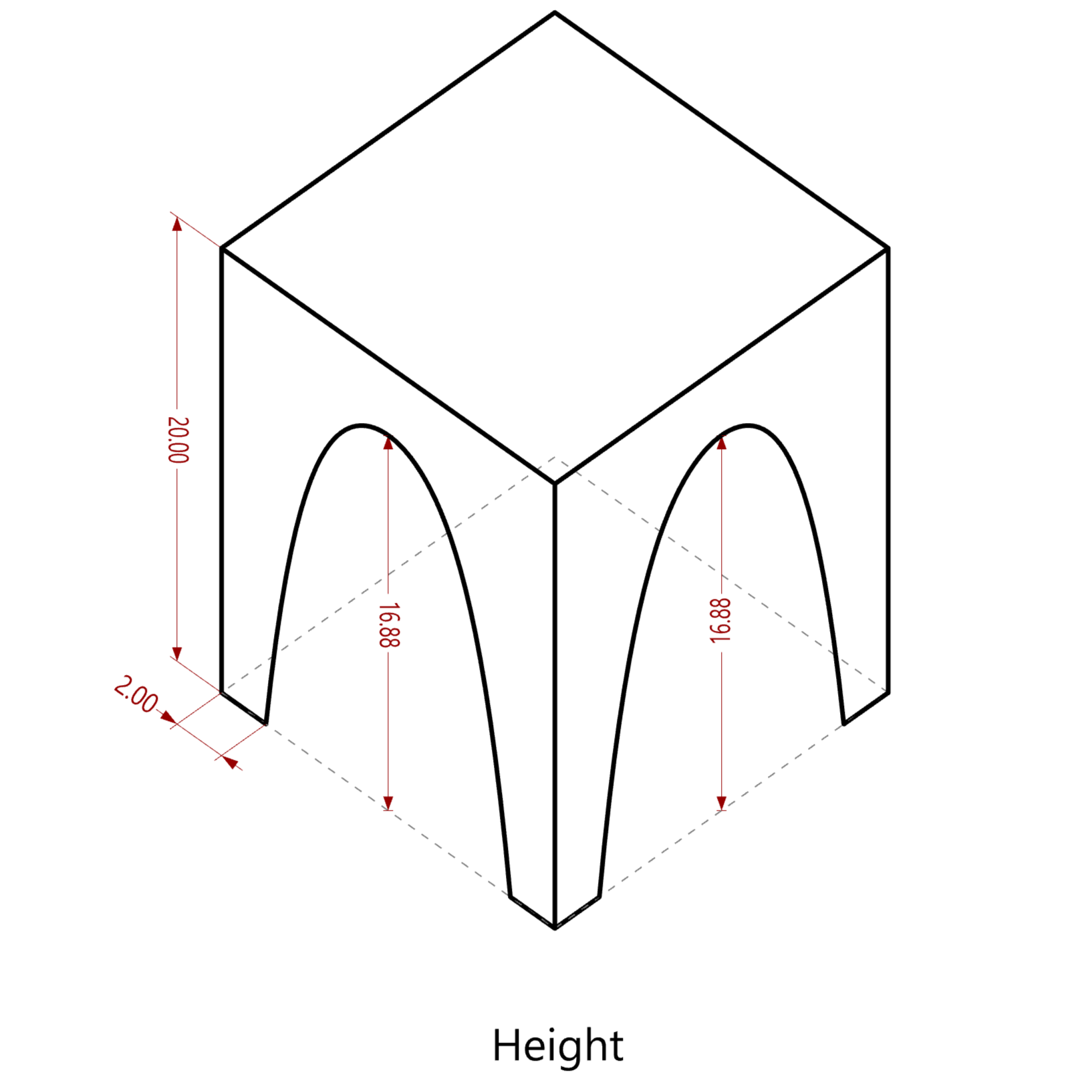
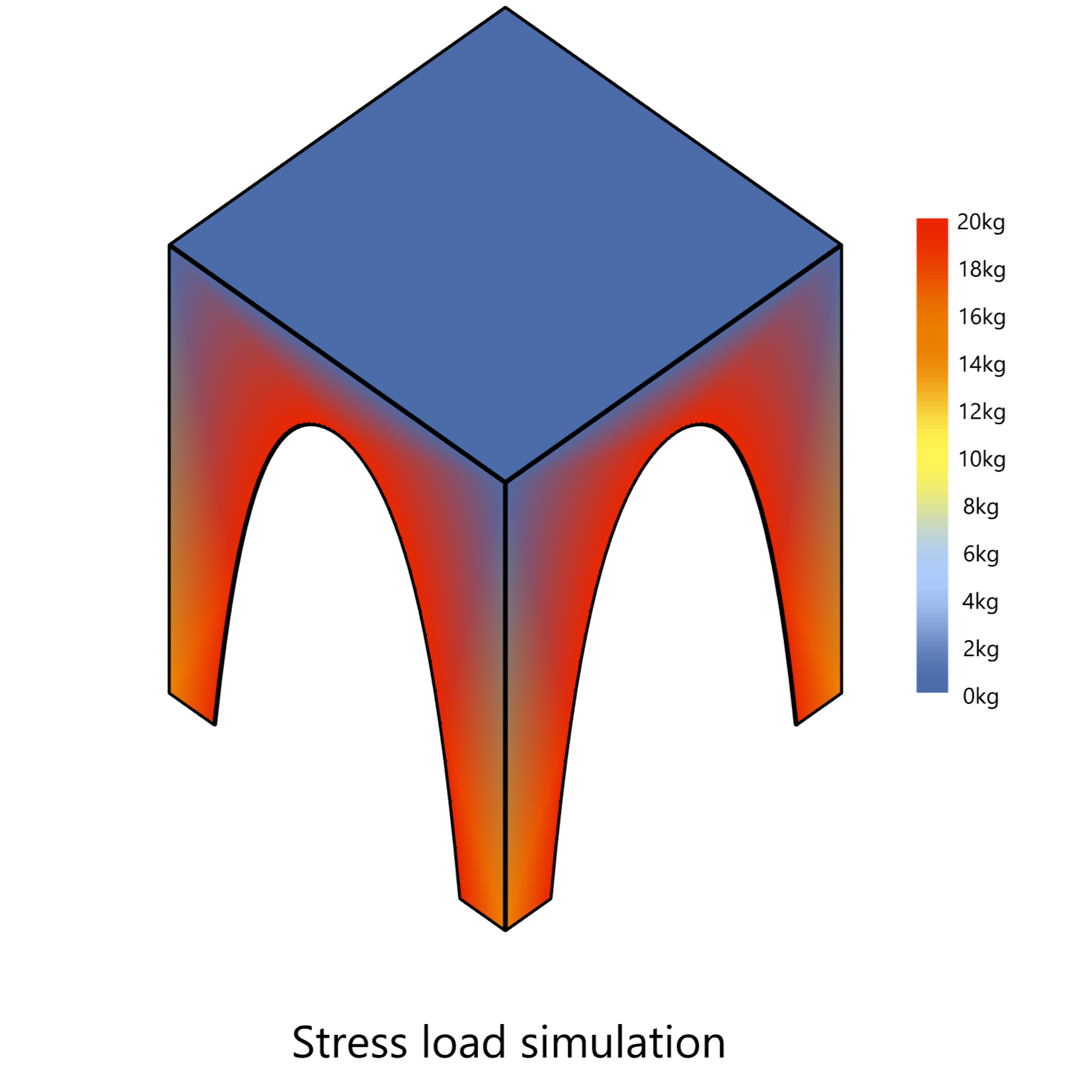
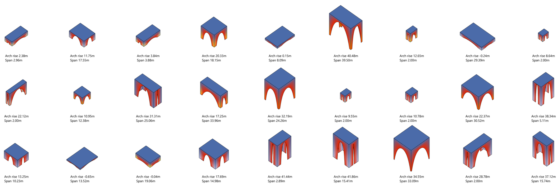
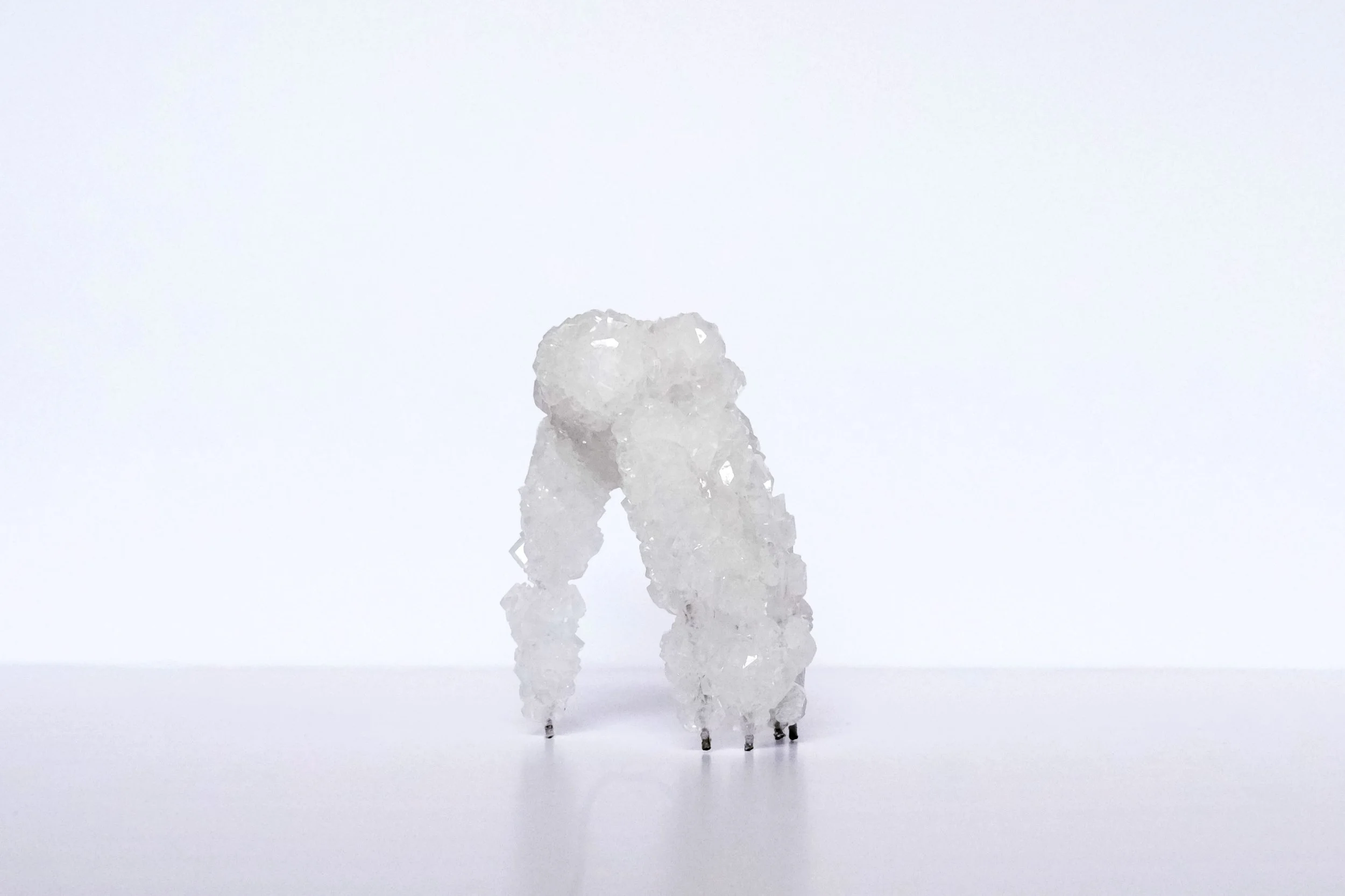
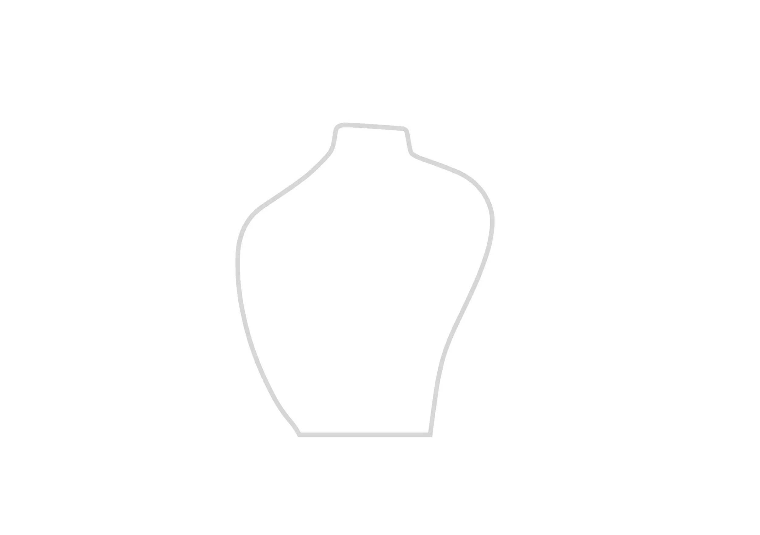
01 COMPUTATION
Catenary structural study
Catenary arches were used as the base geometry because they carry loads primarily in compression, making them inherently stable as crystals accumulate along the surface. A parametric system in Rhino/Grasshopper varied arch count, rise, span, thickness, and height to generate a family of arch-based forms. Stress load simulations identified geometries that distribute structural loads efficiently and promote even crystal deposition, reducing local stress concentrations and the risk of collapse during crystallization.
Key Insights Geometries distributing load through continuous catenary curvature produced the lowest stress concentrations and guided the physical mold development.
Performance Insights • Continuous catenary curvature minimized stress concentration • Higher arch rise increased edge compression but reduced mid-span stress • Thicker top plates reduced overall deformation
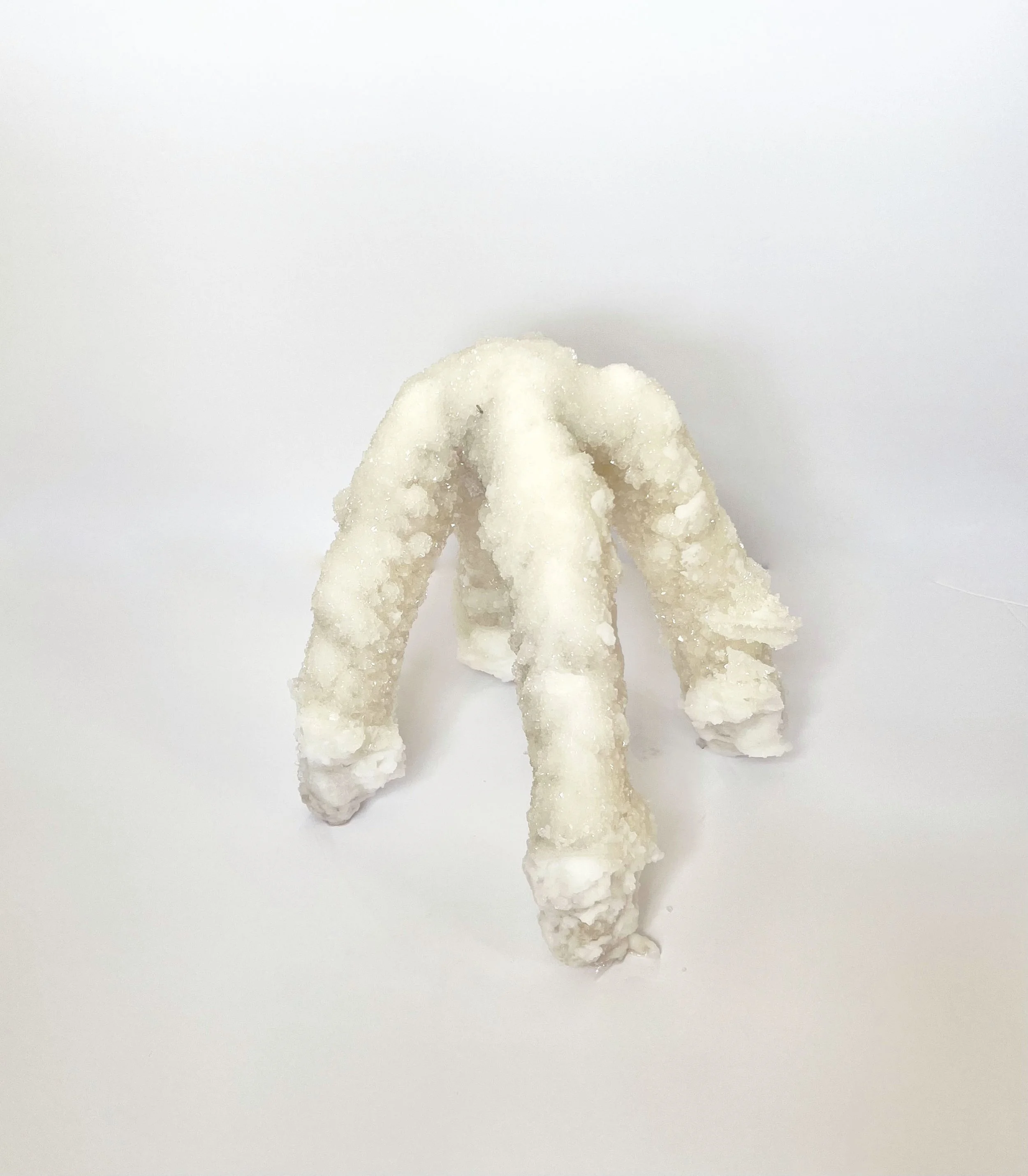
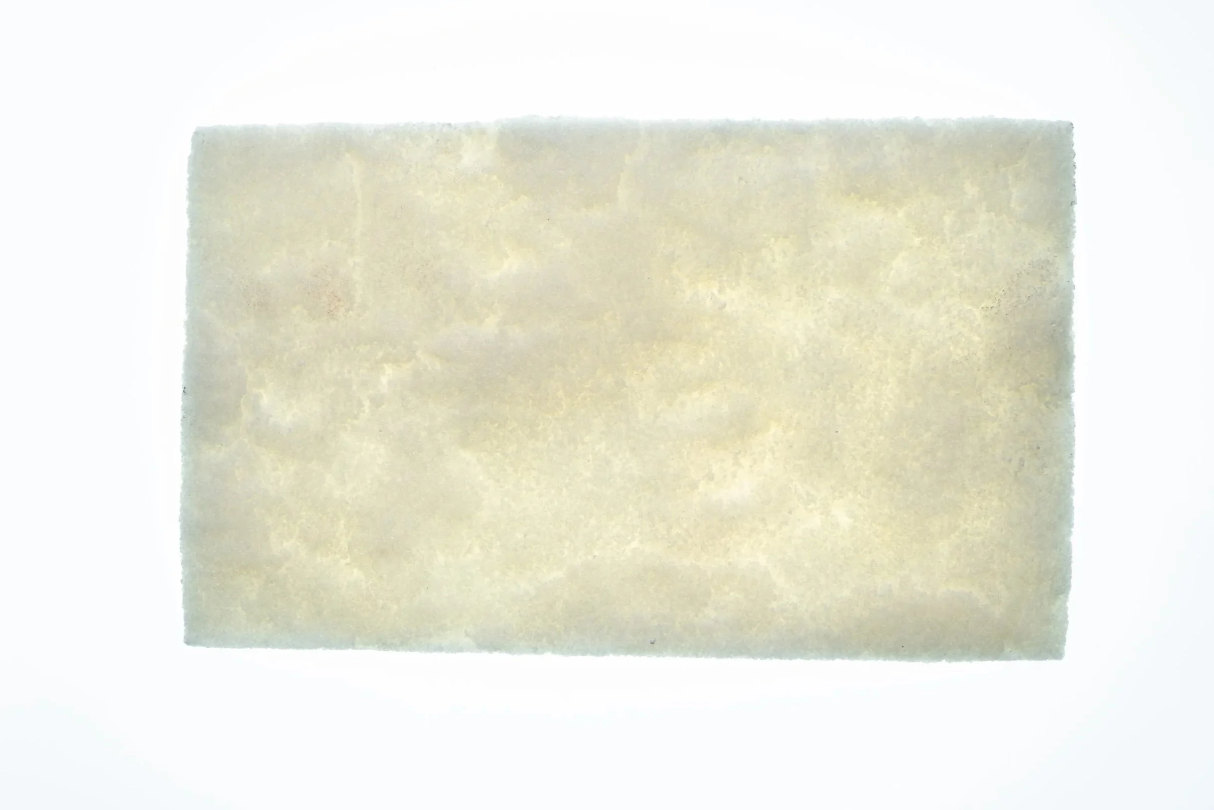
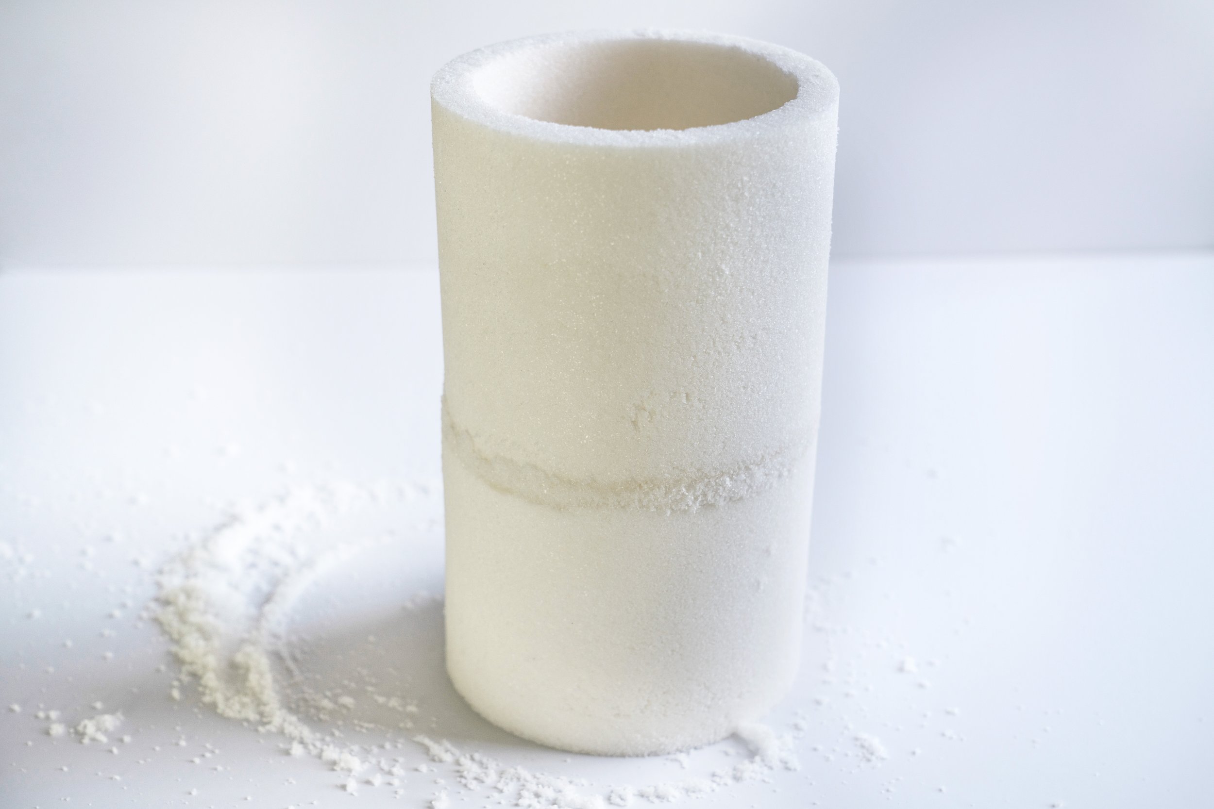
02 MATERIAL RESEARCH: CRYSTALLIZATION
Crystal growth on structural frameworks
Supersaturated salt solutions were used to study how different armature geometries guide crystal formation. By varying mesh scale, fiber tension, and immersion duration, the experiments showed how structure affects crystal density, translucency, and stability. These insights informed the geometry selection for subsequent crystallized forms.
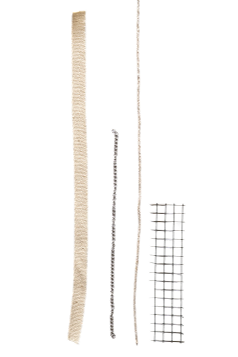
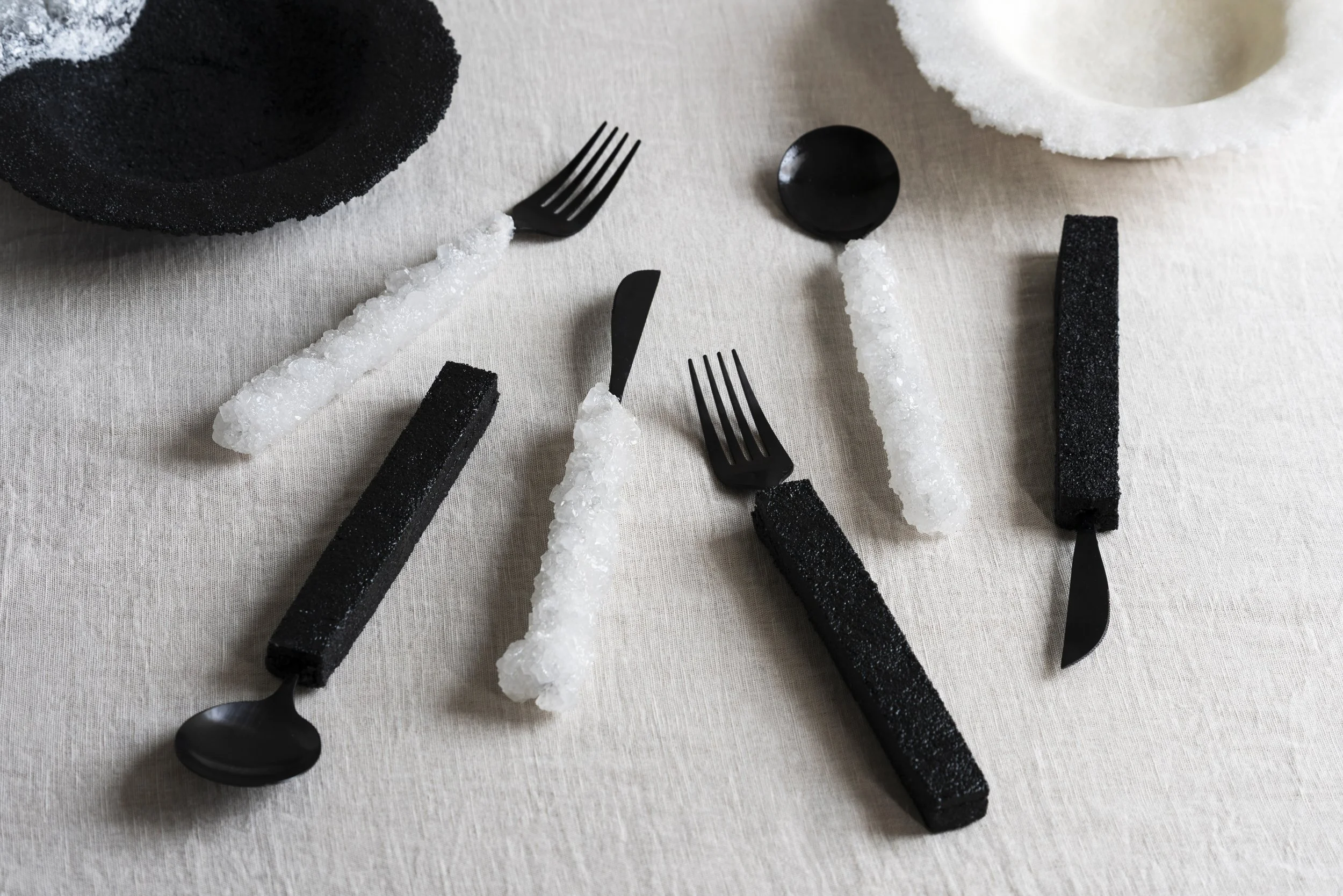
From top: cotton rope, steel chain, cotton thread, steel wire mesh
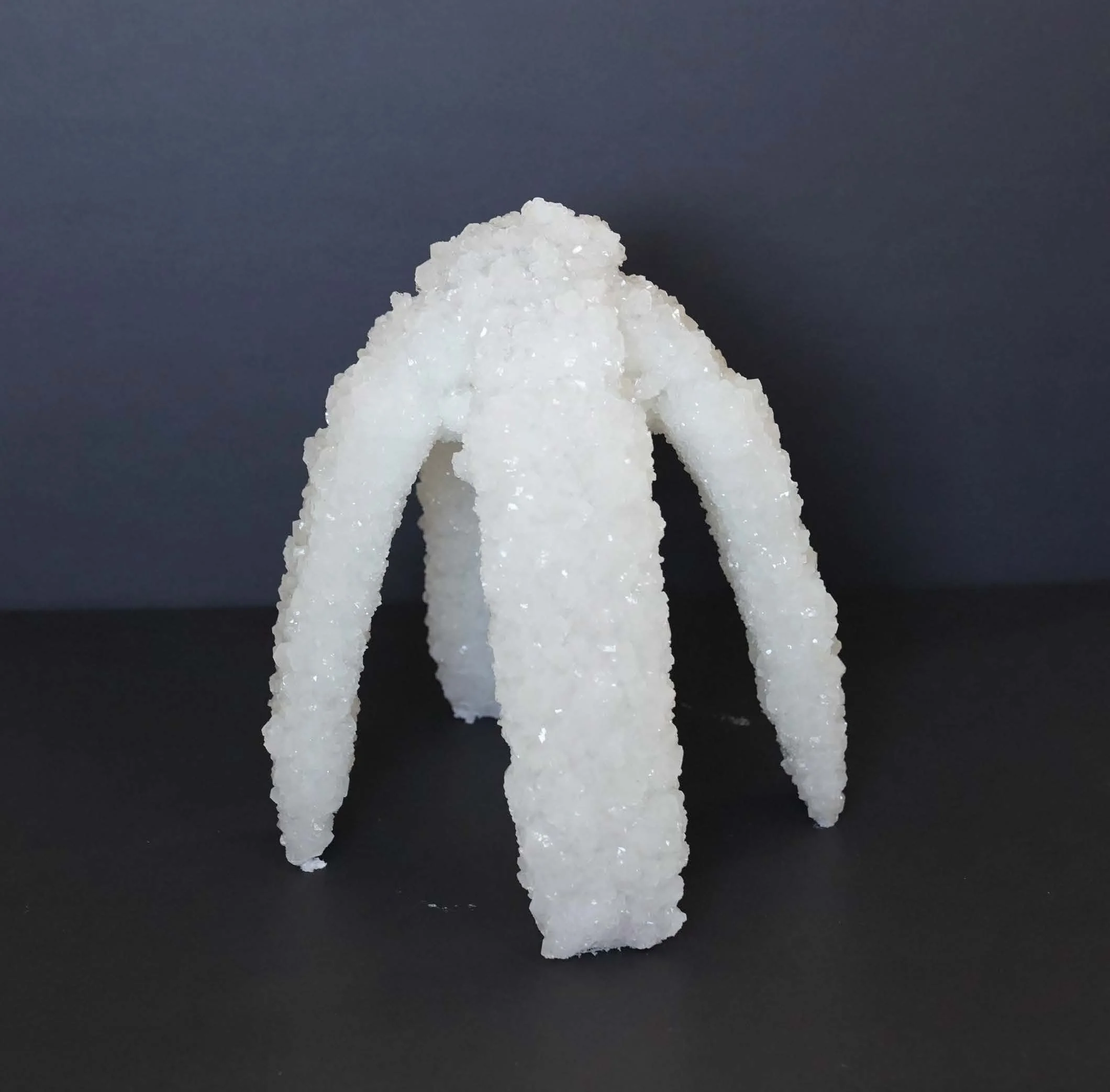
Variations in crust thickness, surface texture, and structural stability.
Crystallization Process Steel and fiber-based armatures were submerged in supersaturated salt solutions (380 g/L). Crystals nucleated and accumulated across the frameworks over 7–14 days. Growth patterns were controlled through solution concentration, temperature, and orientation.
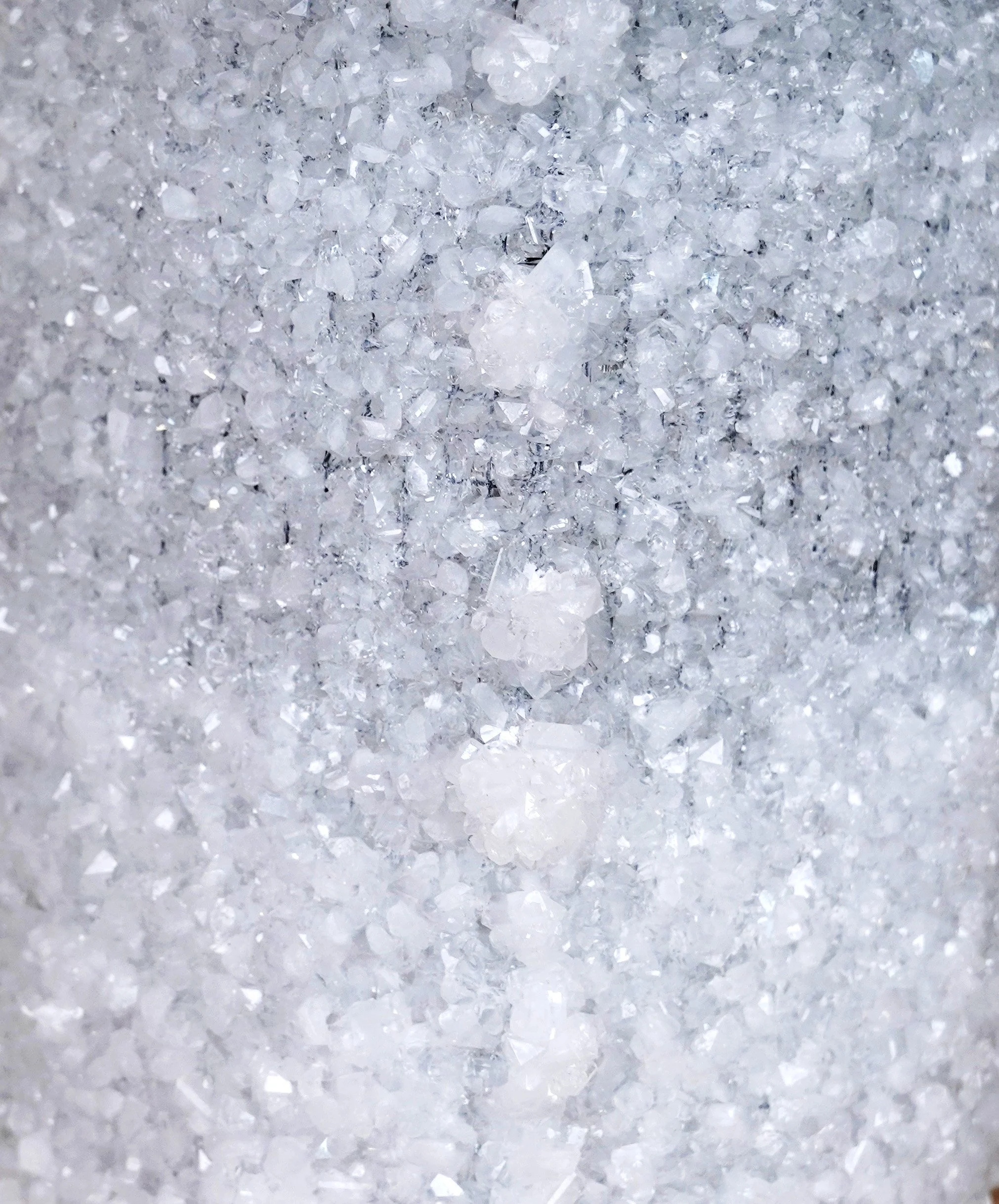
Material Properties Observed Translucency: Crystal layers between 3–8 mm diffuse light and soften silhouettes. Structure: Interlocking crystal aggregates stiffen thin meshes and create self-supporting forms. Aesthetic: Faceted crystalline surfaces refract light, producing shimmering gradients and spatial depth.
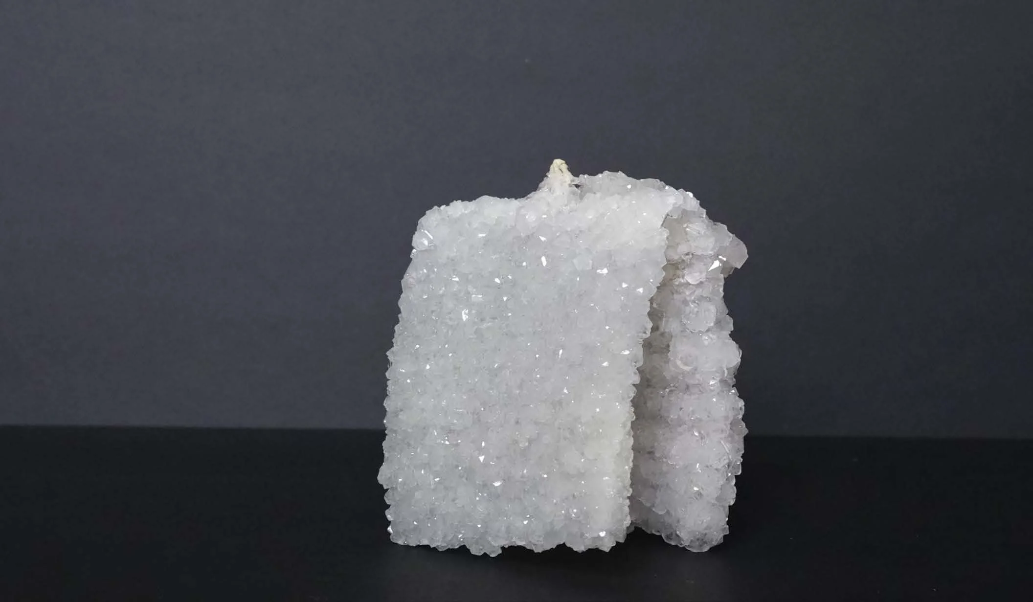
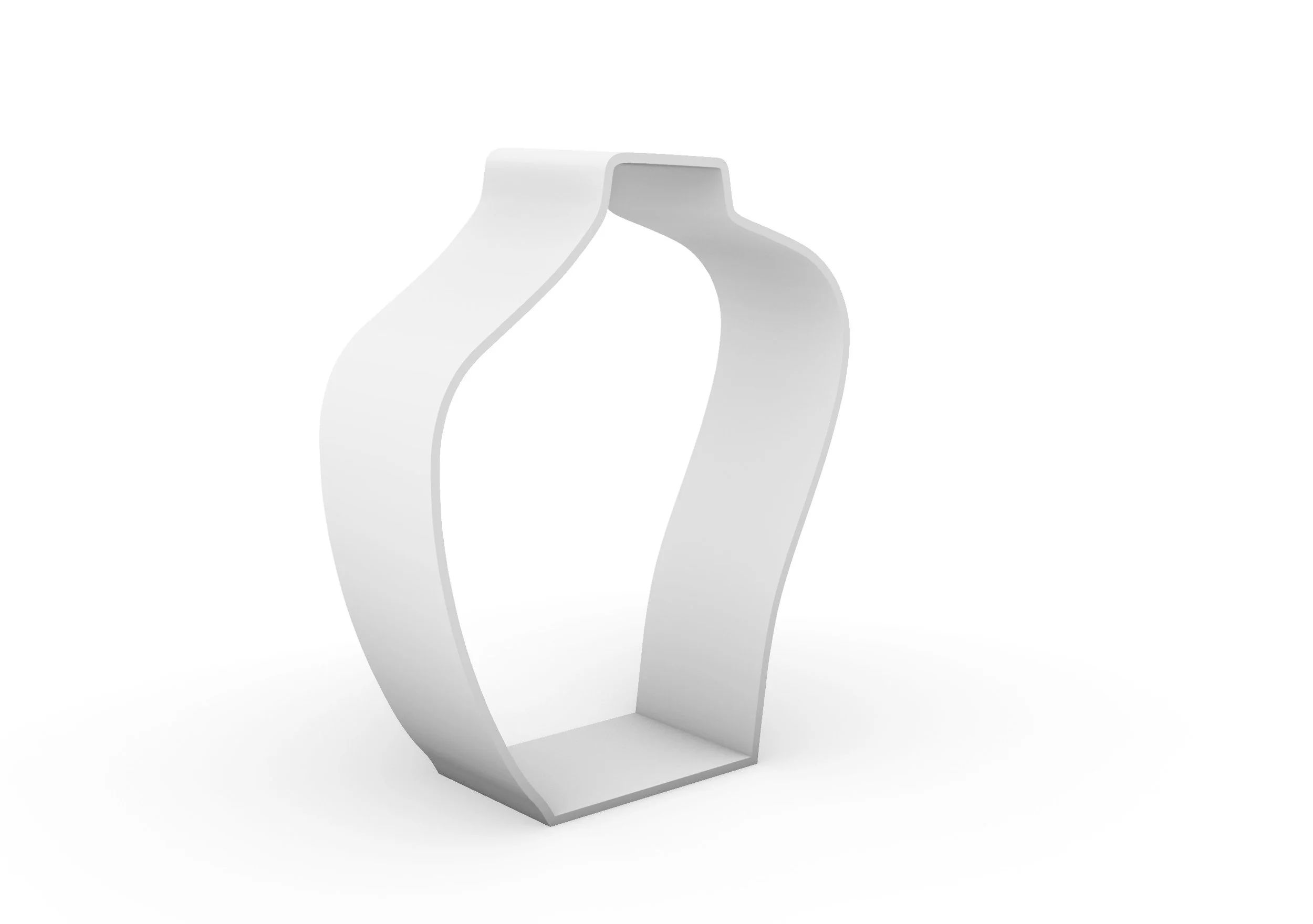
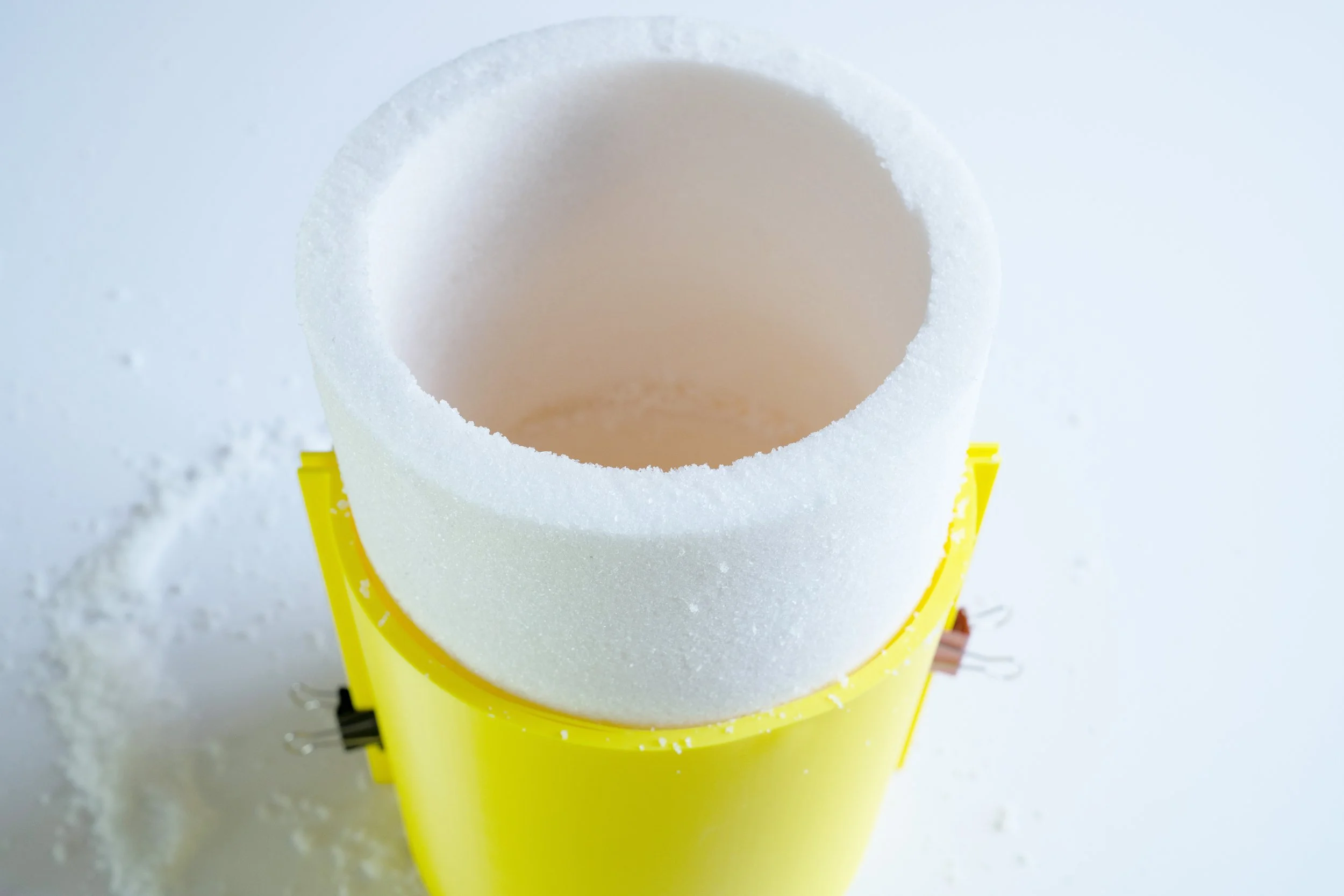
03 FABRICATION: TABLE DESIGN
Crystallized mesh forms
A steel wire mesh form was cut to match the selected catenary geometry and used as the structural base for crystallization. The mesh provided both rigidity and porosity, allowing the supersaturated salt solution to circulate through the form during submersion. Over several days, crystals nucleated along the mesh strands and gradually built into a continuous shell. The final crystallized form retained the underlying catenary structure while gaining volume and surface density.
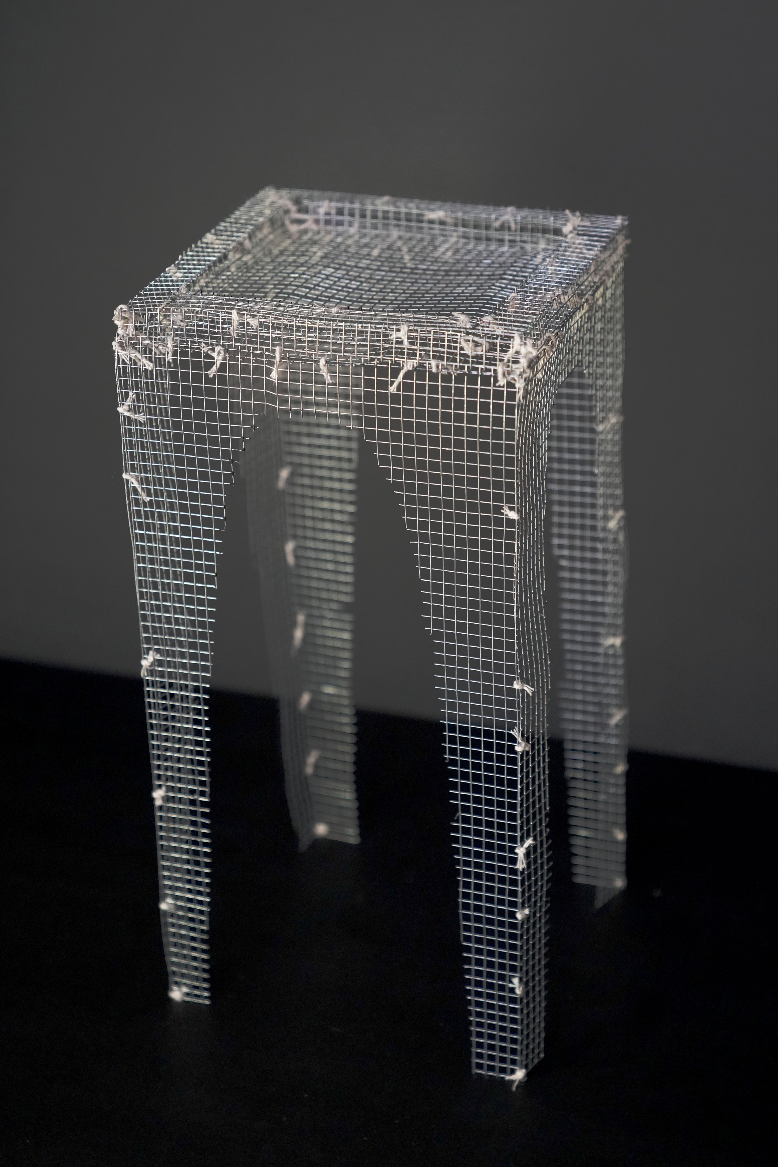
Mesh armature before submersion
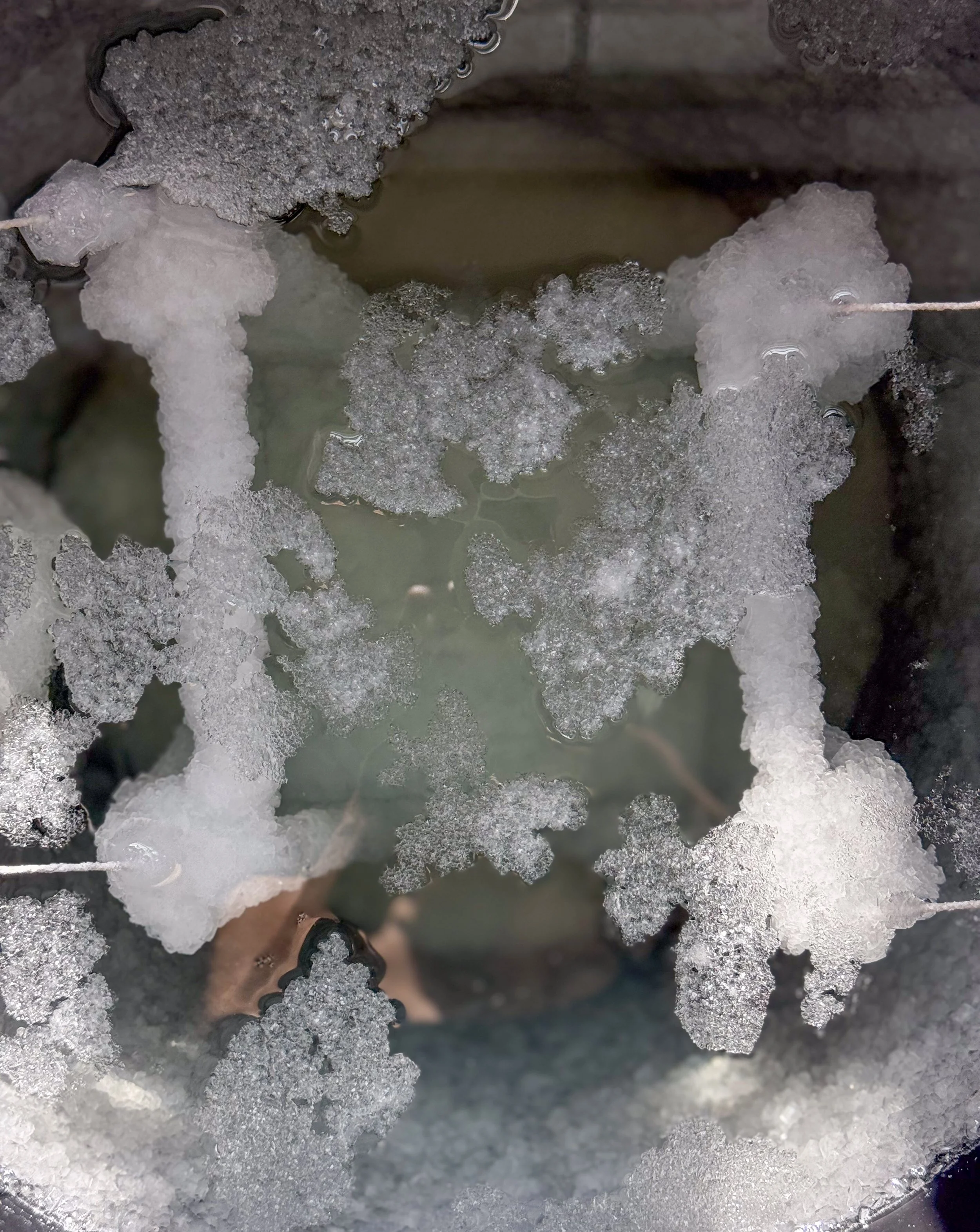
Crystal growth in progress
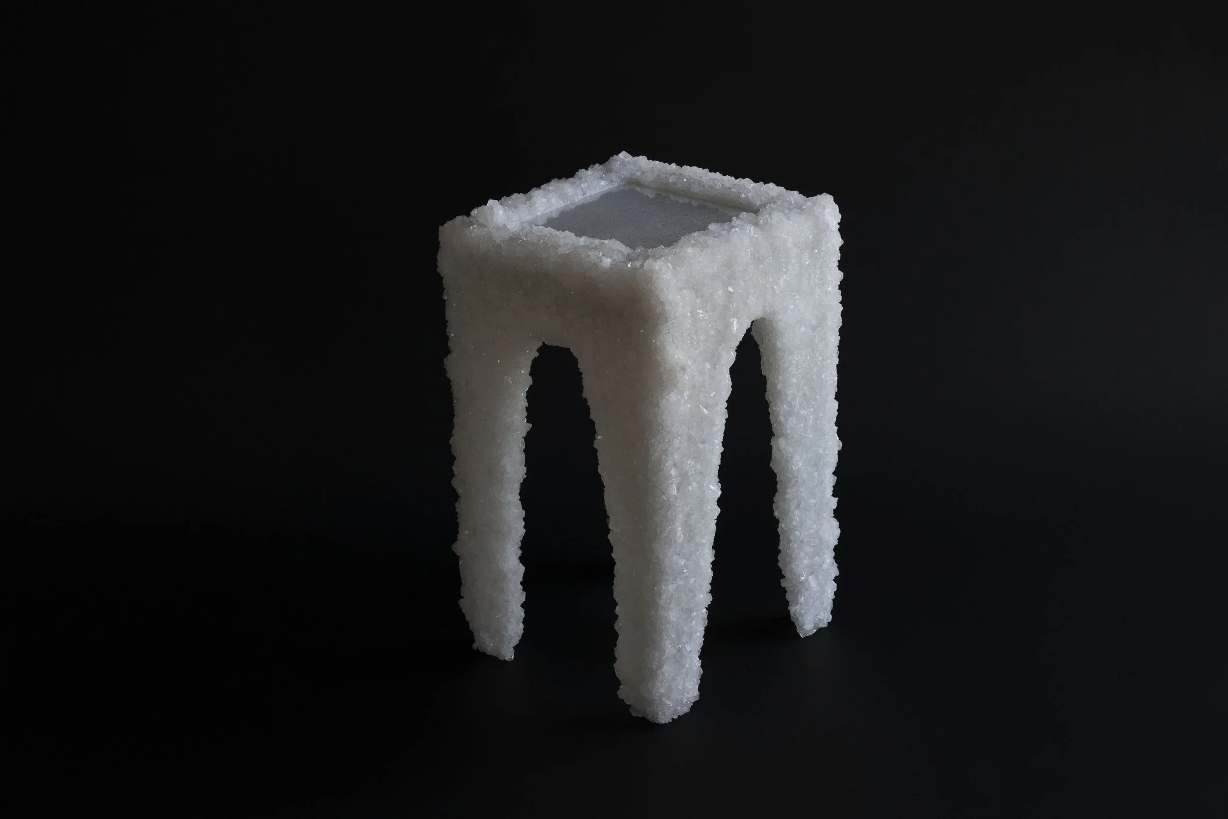
23x23x39cm
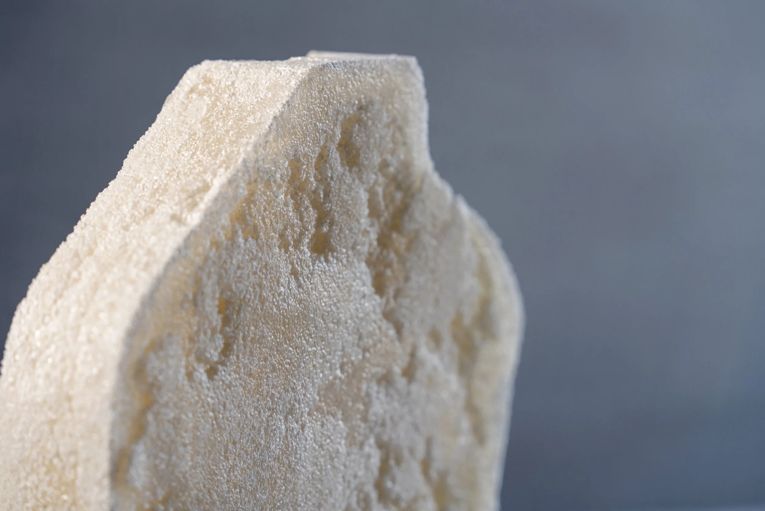
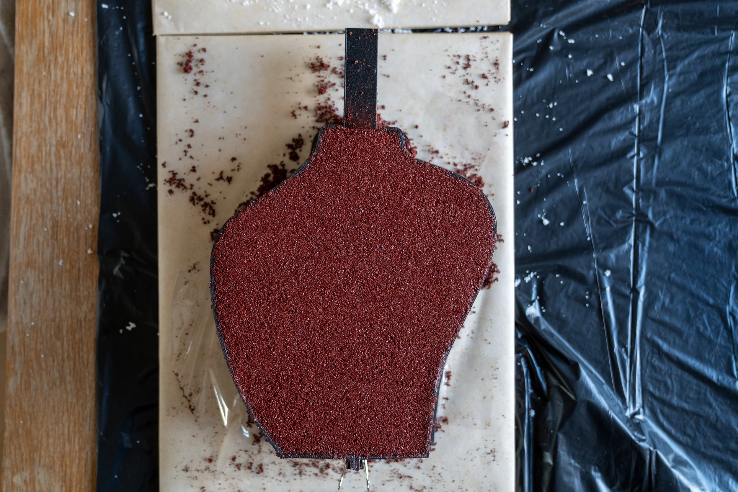
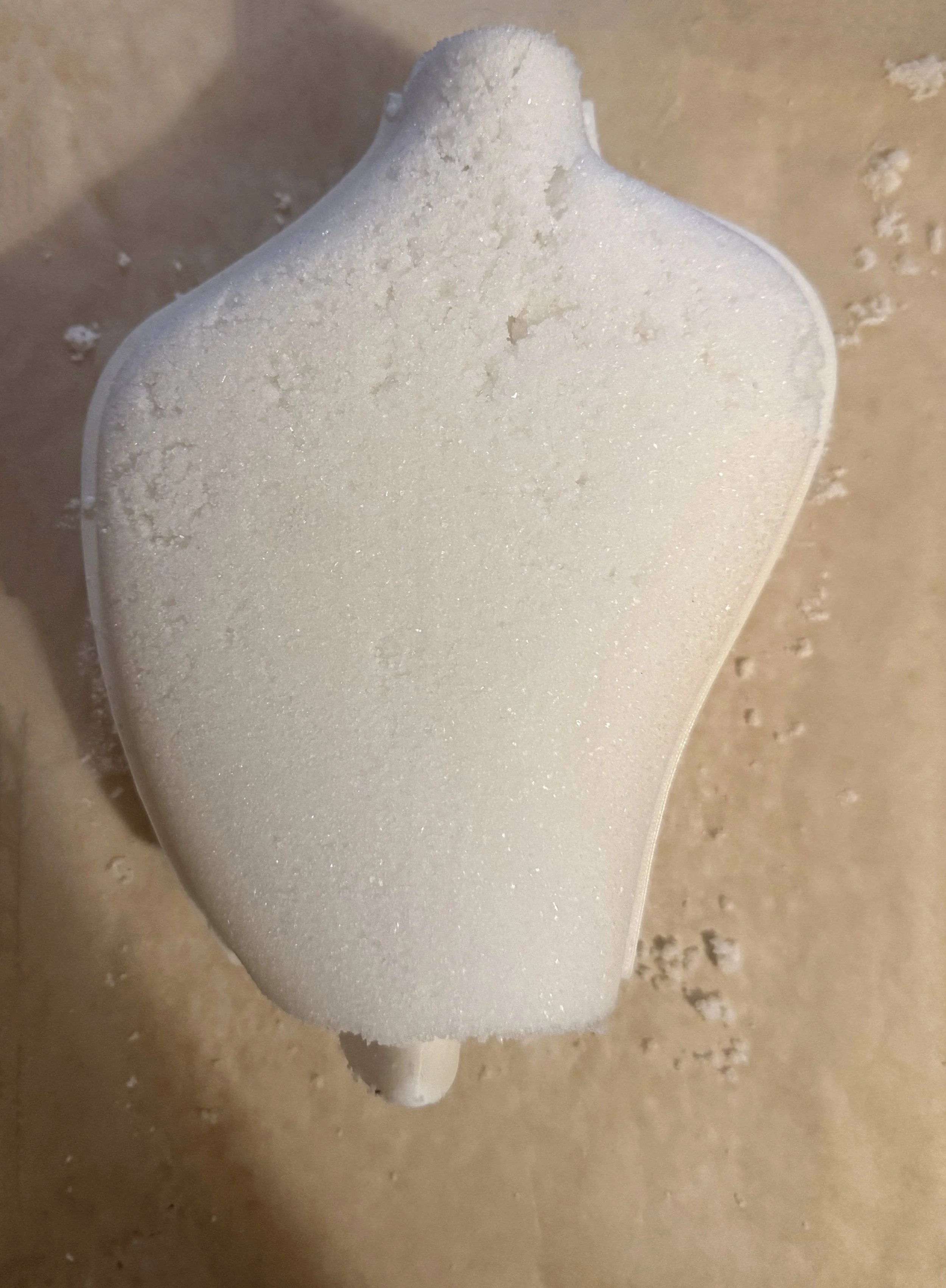
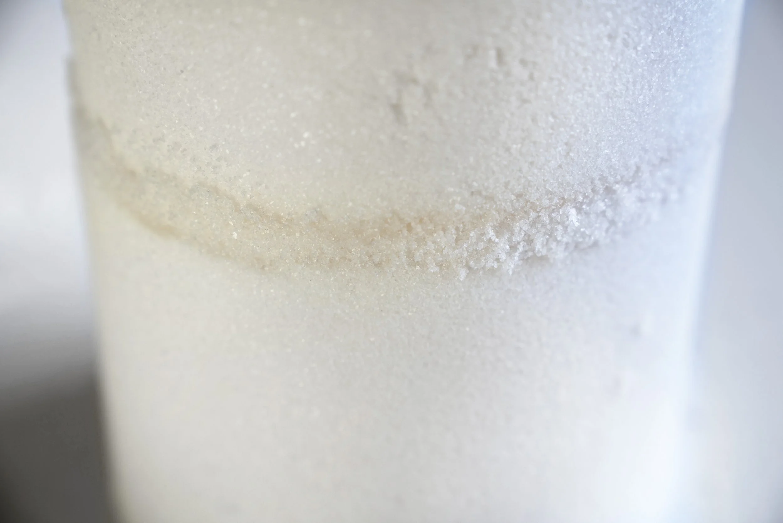
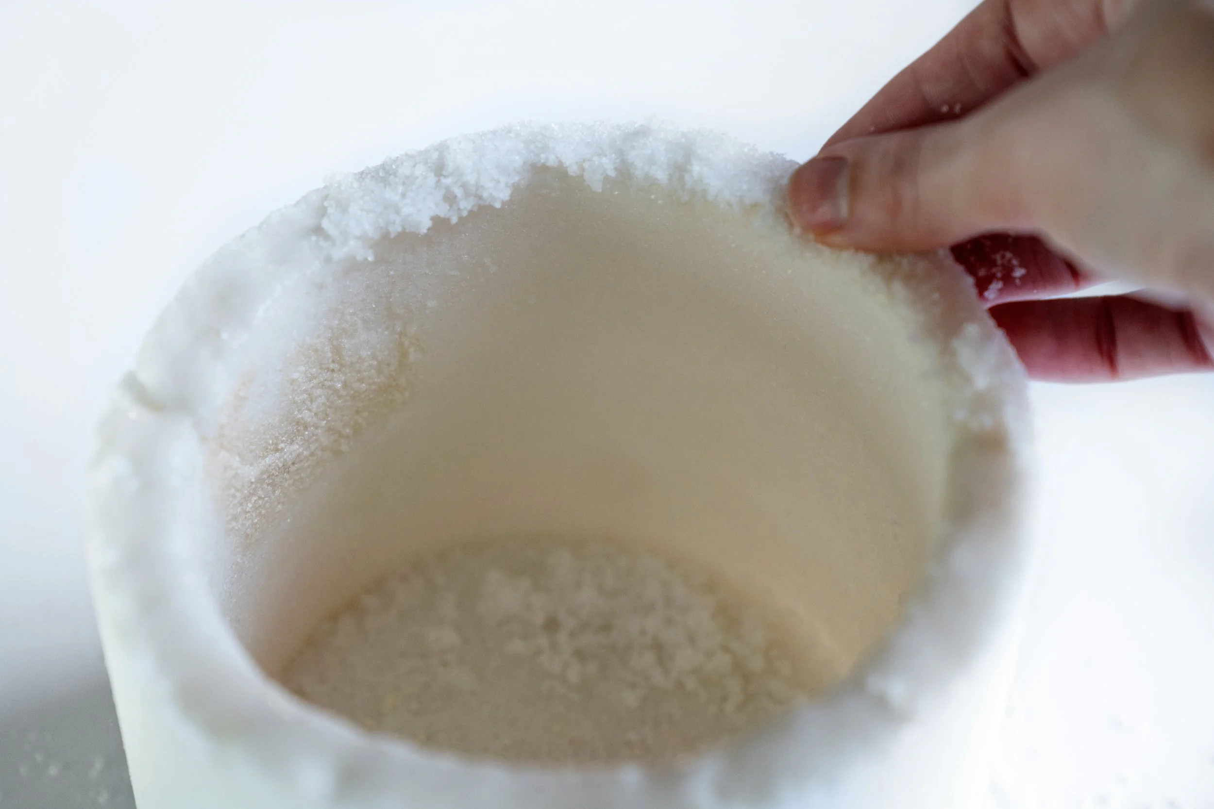
04 MATERIAL RESEARCH: SEA SALT COMPOSITES
Binder and ratio experiments
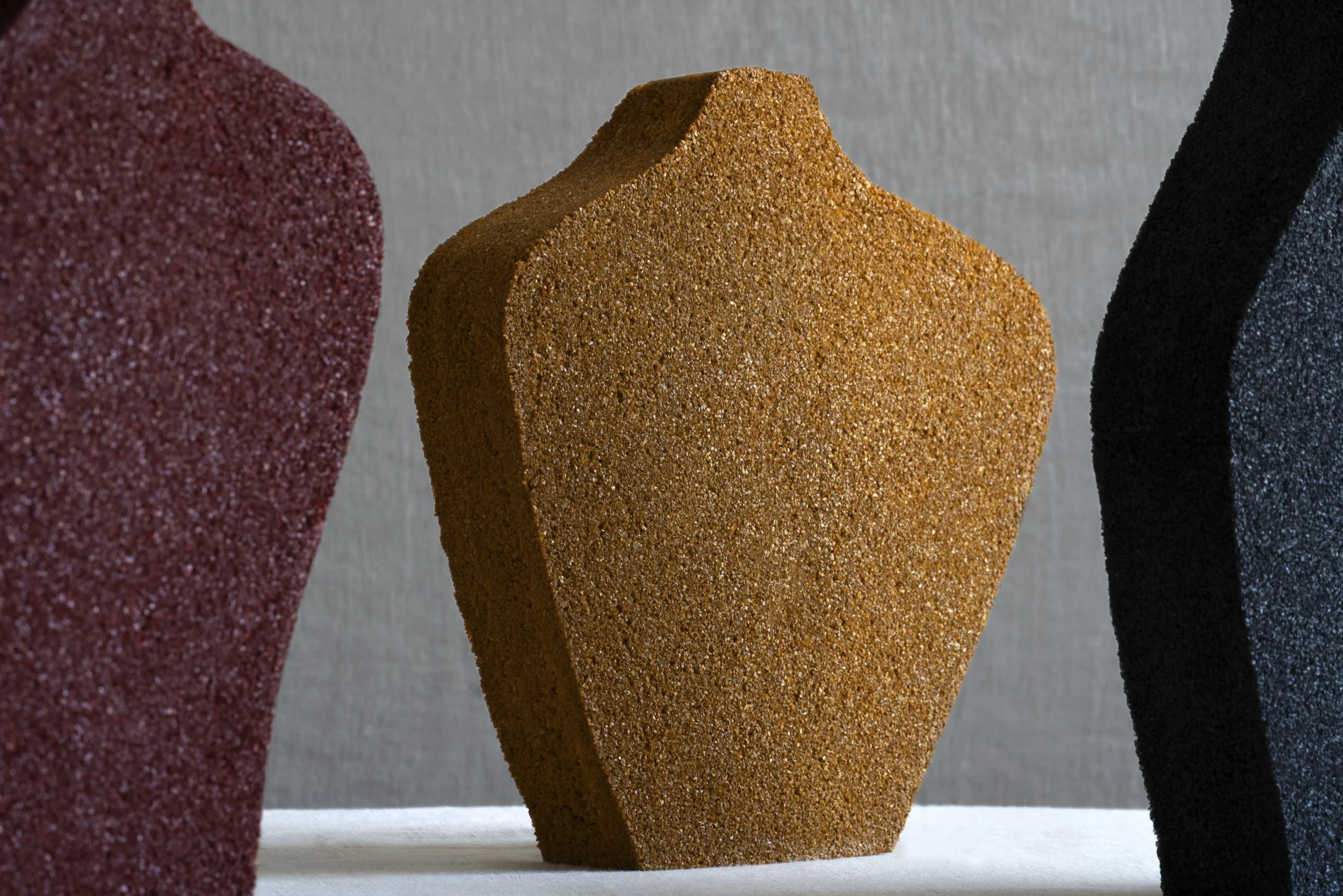
A salt composite was developed by testing more than twenty formulations that combined sea salt with different binders. Each mix produced different behaviors in strength, brittleness, shrinkage, curing rate, and translucency. Controlled testing led to a bio-based composite that cures reliably with a smooth surface finish, balancing structural integrity with light diffusion.
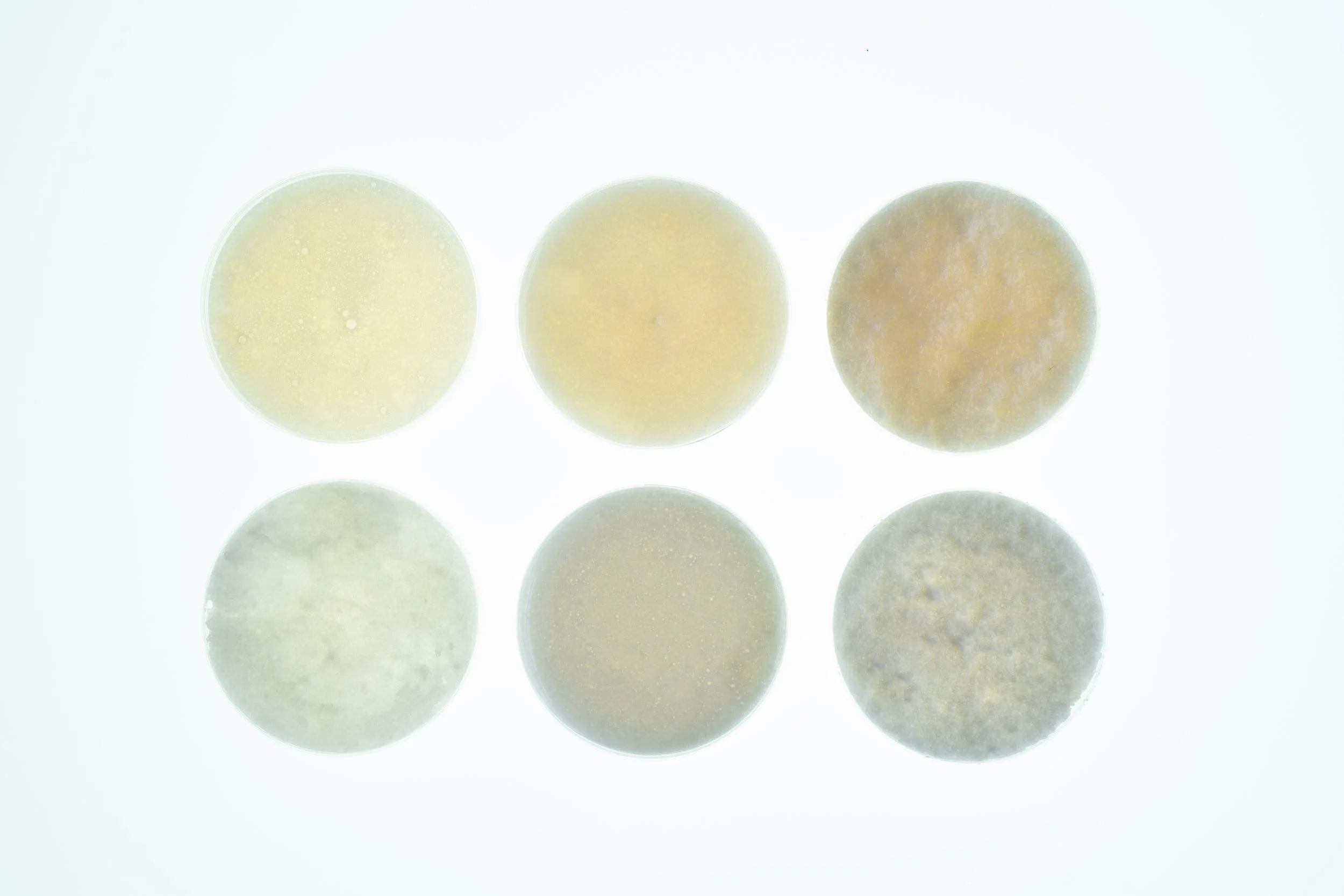
Sample discs showing variations in translucency, density, and surface finish across formulations
Assessing Structural Integrity Protein- and carbohydrate-rich binders created cohesive but brittle samples. Glycerin increased flexibility but dried unevenly. Cornstarch gave strong early bonds but high shrinkage. These results defined which formulations could scale to larger, stable forms.
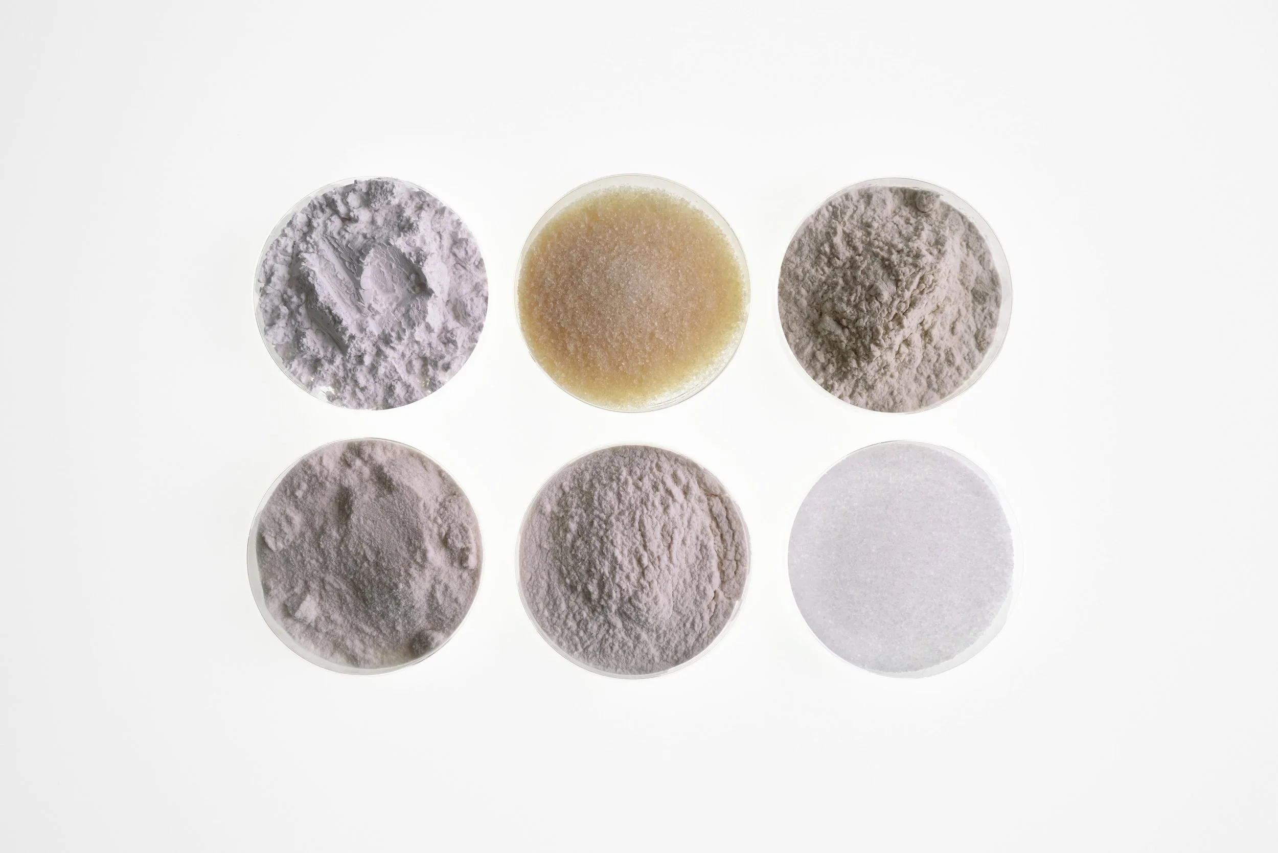
Binders tested: calcium carbonate, gelatin, agar, glycerin, cornstarch, sea salt
Mechanical and Optical Behaviors Binder ratio and drying conditions affected granularity, translucency, and internal density, revealing how concentration and moisture shape crystal packing and surface texture.
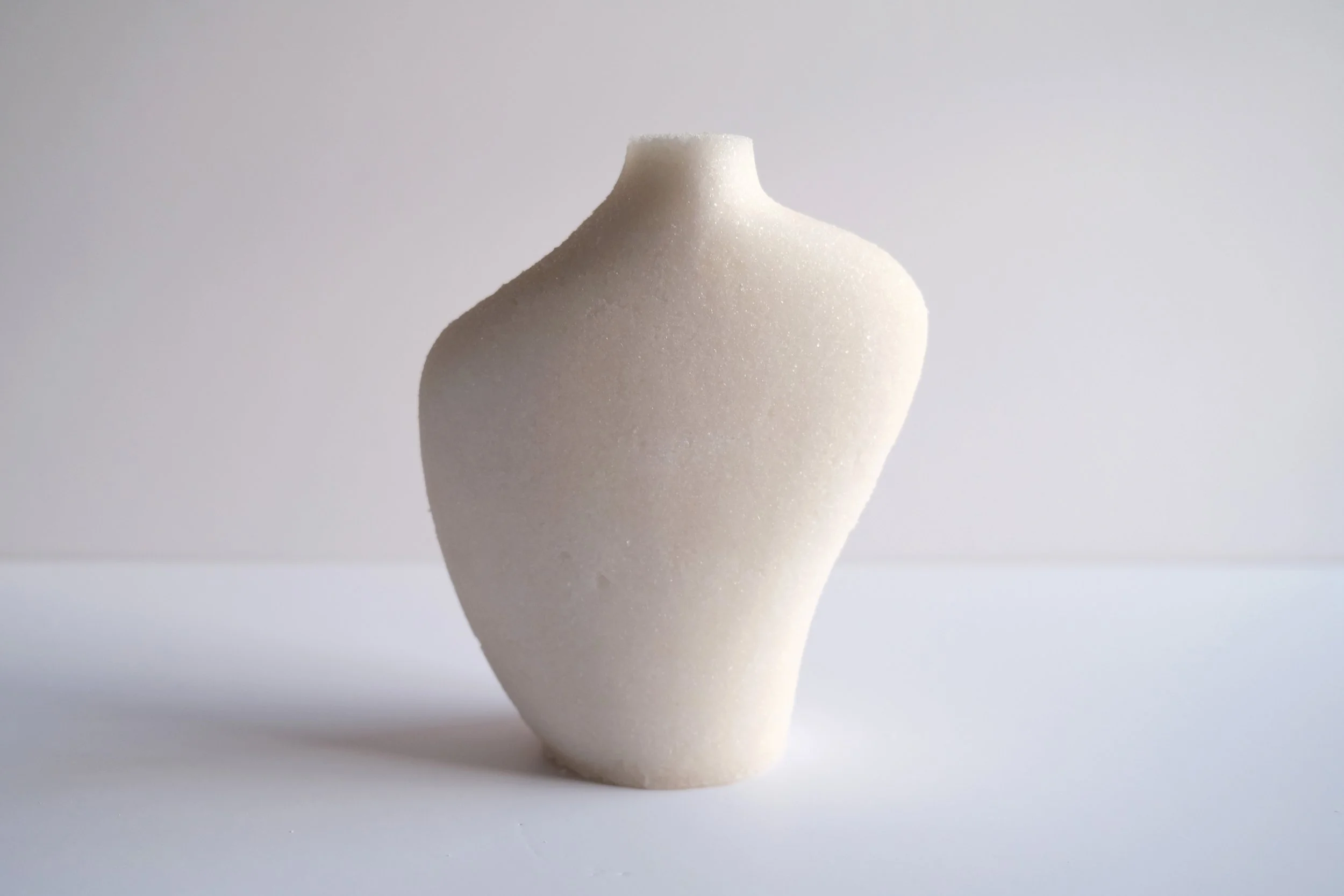
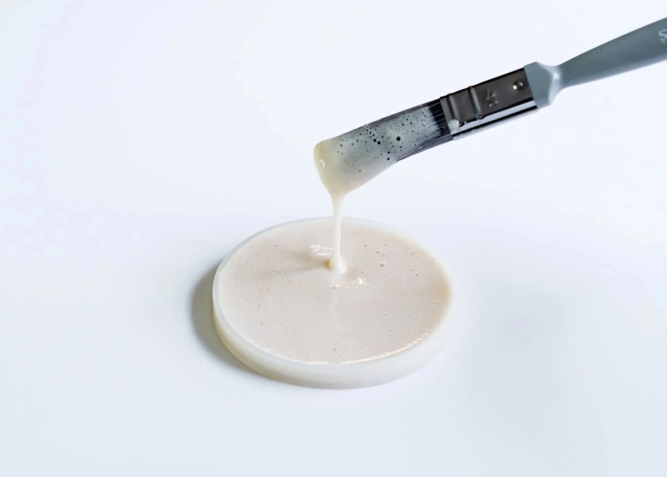
05 MATERIAL RESEARCH: SEA SALT COMPOSITES
Material testing led to a single bio-based binder system that became the base composite for all subsequent prototypes.
Final output 80:20 sea salt to bio-binder | low shrinkage | high structural cohesion | stable curing | soft, diffused translucency
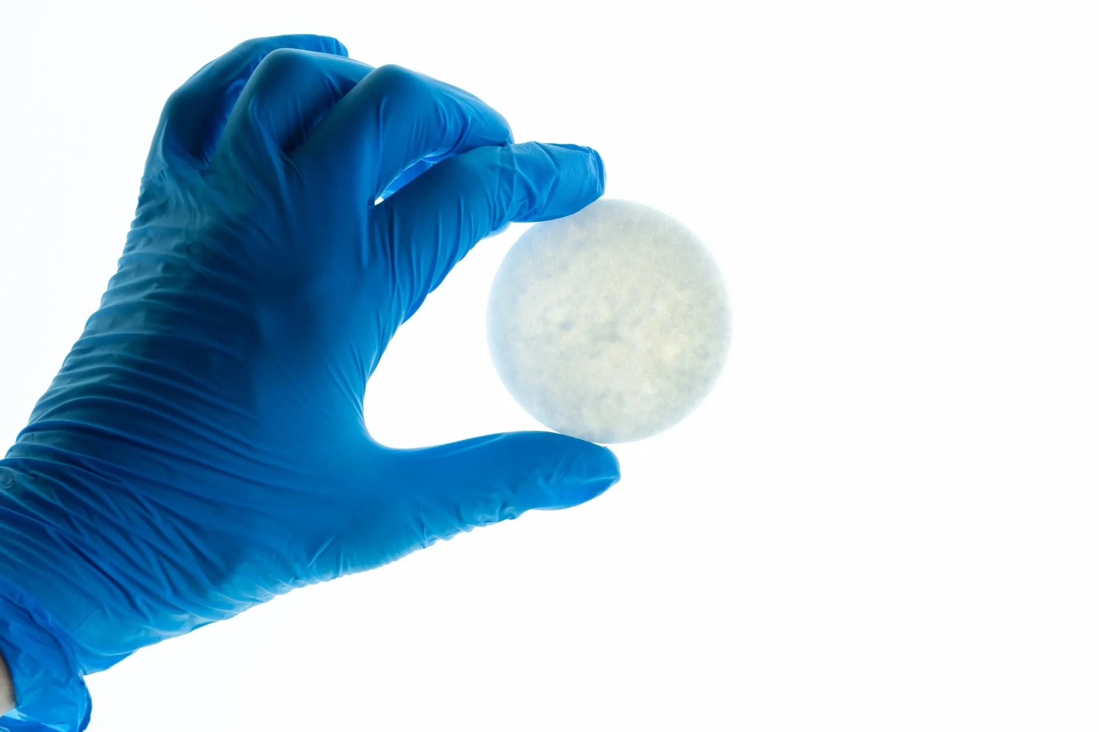
Optimized composite ratio
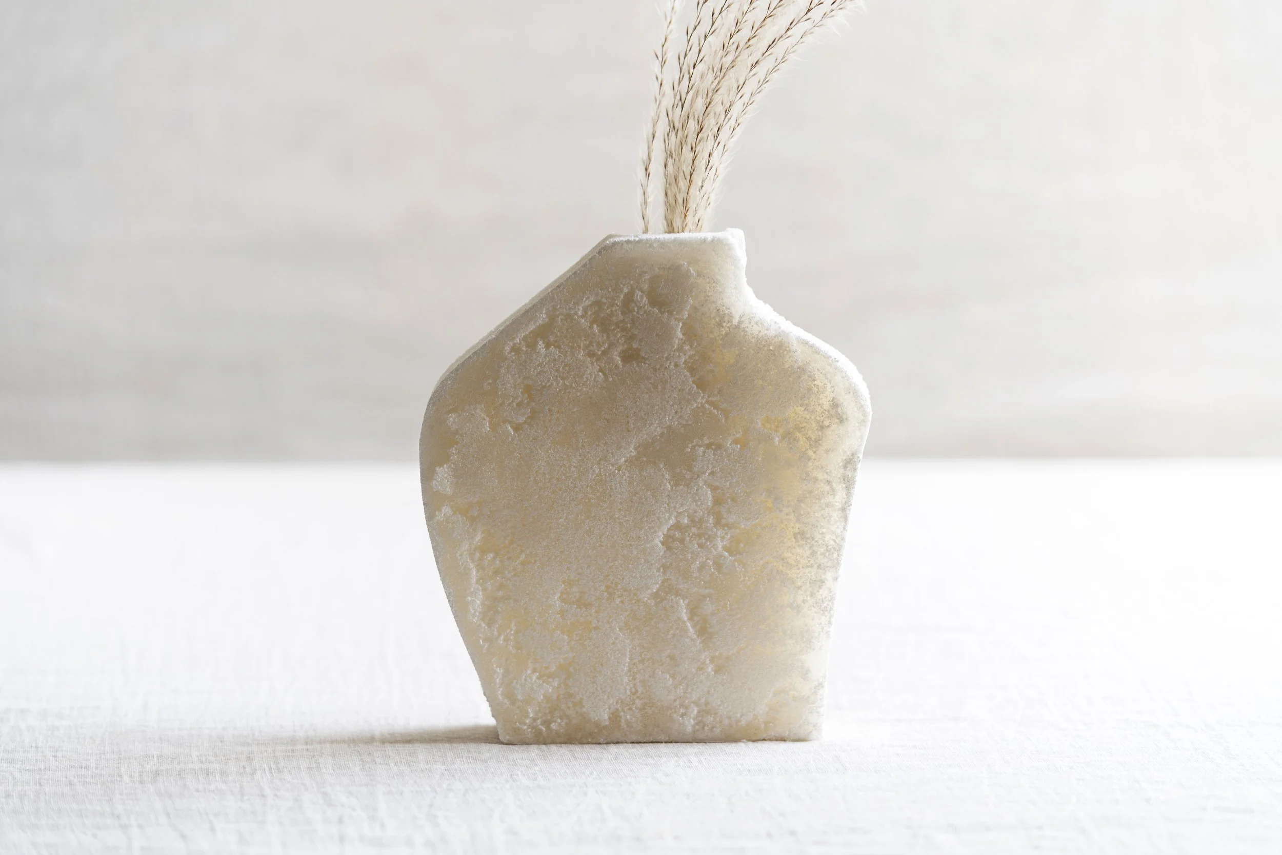
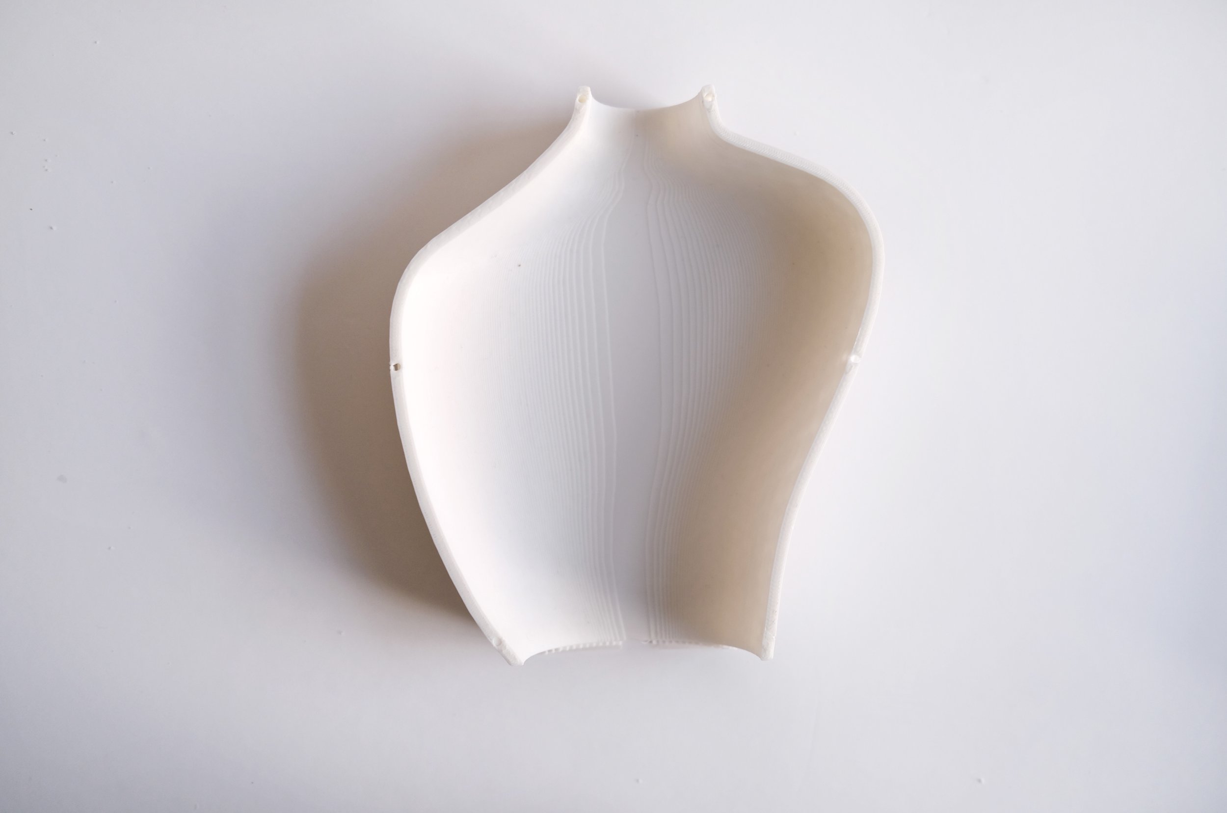
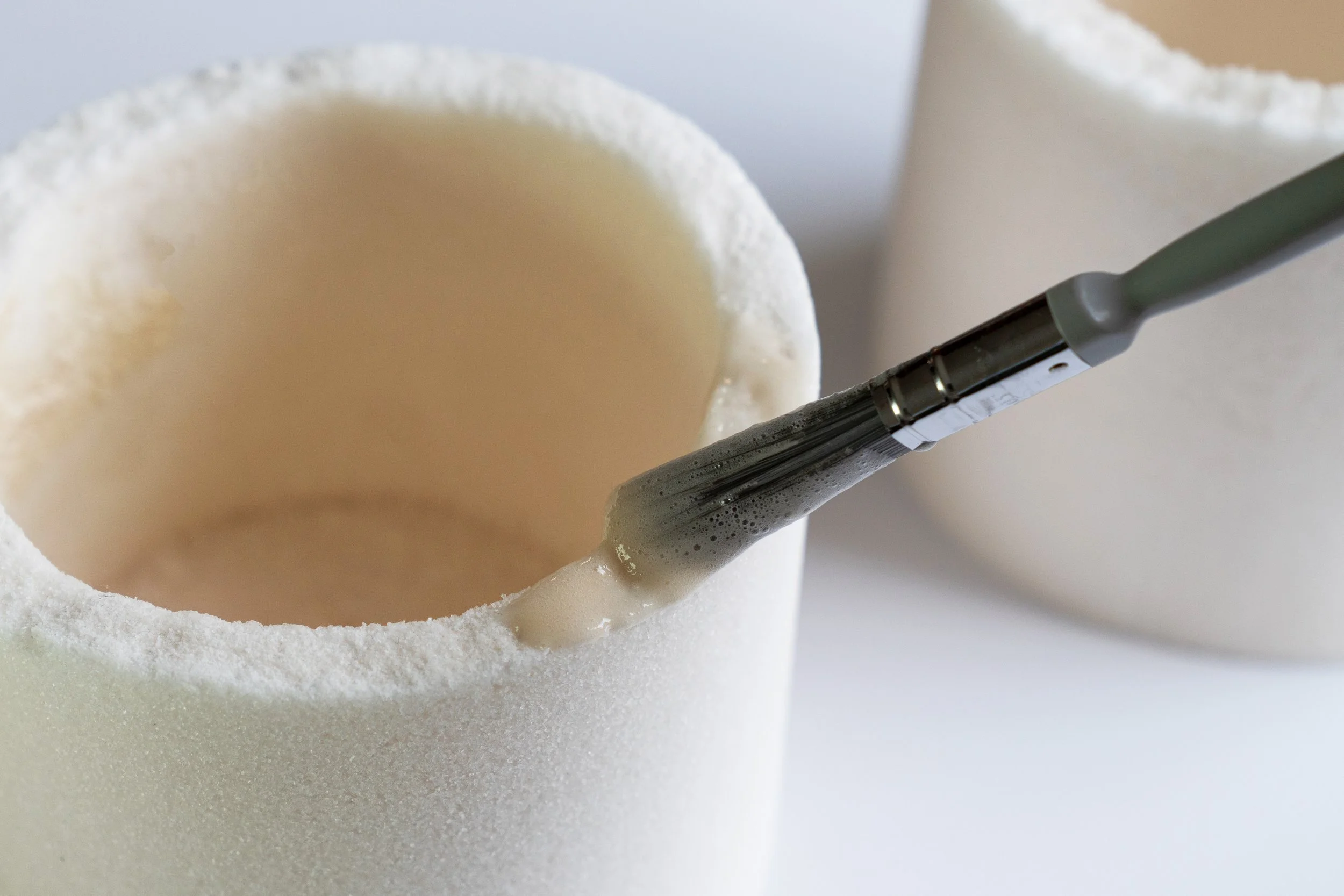
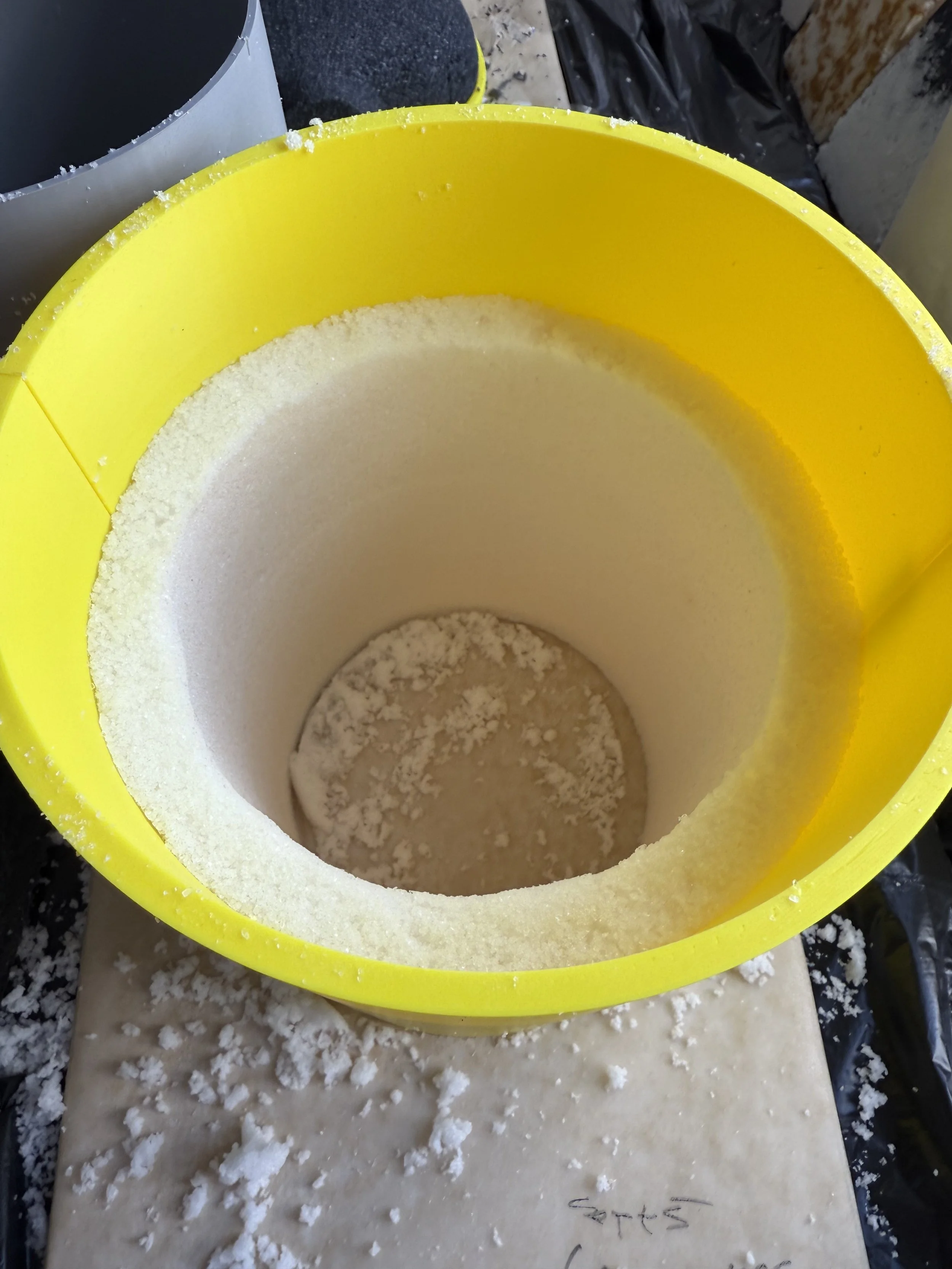
06 FABRICATION: VESSEL FORMS
Digital to physical development
The vessel workflow began with 2D profiles modeled in Rhino, constrained by the behavior of the salt composite. Early formulations limited profiles to shallow, flat silhouettes; taller or more curved geometries collapsed during curing. As the composite stabilized through adjusted binder concentration and salt grain ratios, profiles could be extruded into 3D molds supporting rounded volumes and continuous curvature. This feedback between material stability and achievable geometry defined the digital-to-physical pipeline.
Geometry and Mold Development. Mold design required testing single piece and multi-part configurations, evaluating parting line placement against the composite's fragility at different cure stages.
Final Work Flow 01 2D profile in Rhino → 02 3D extrusion → 03 3D-printed mold → 04 casting → 05 curing and final object

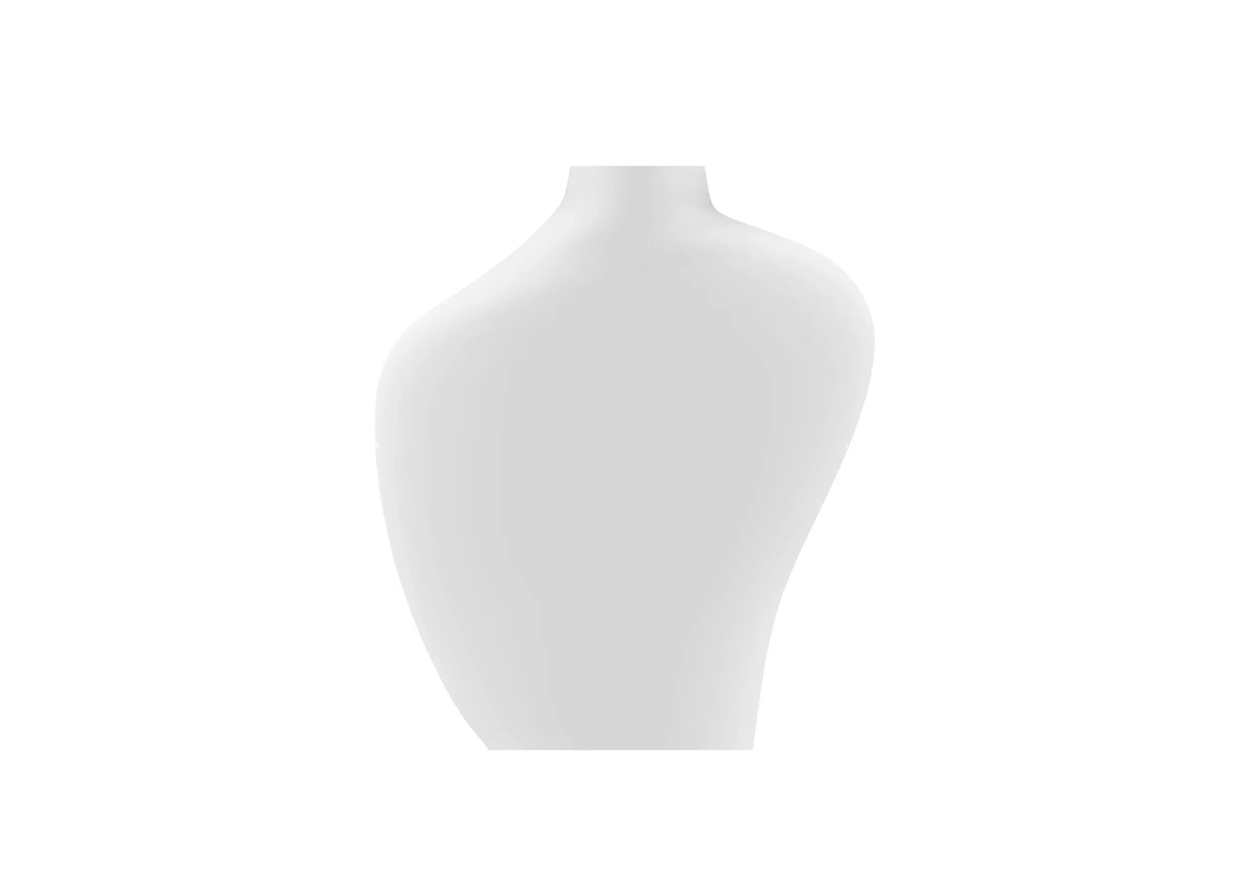
Material ↔ Form Relationship. Early composite ratios supported only shallow or flat forms. Improved formulations allowed taller, rounded vessels to be cast without collapse, linking material stability directly to achievable geometry.
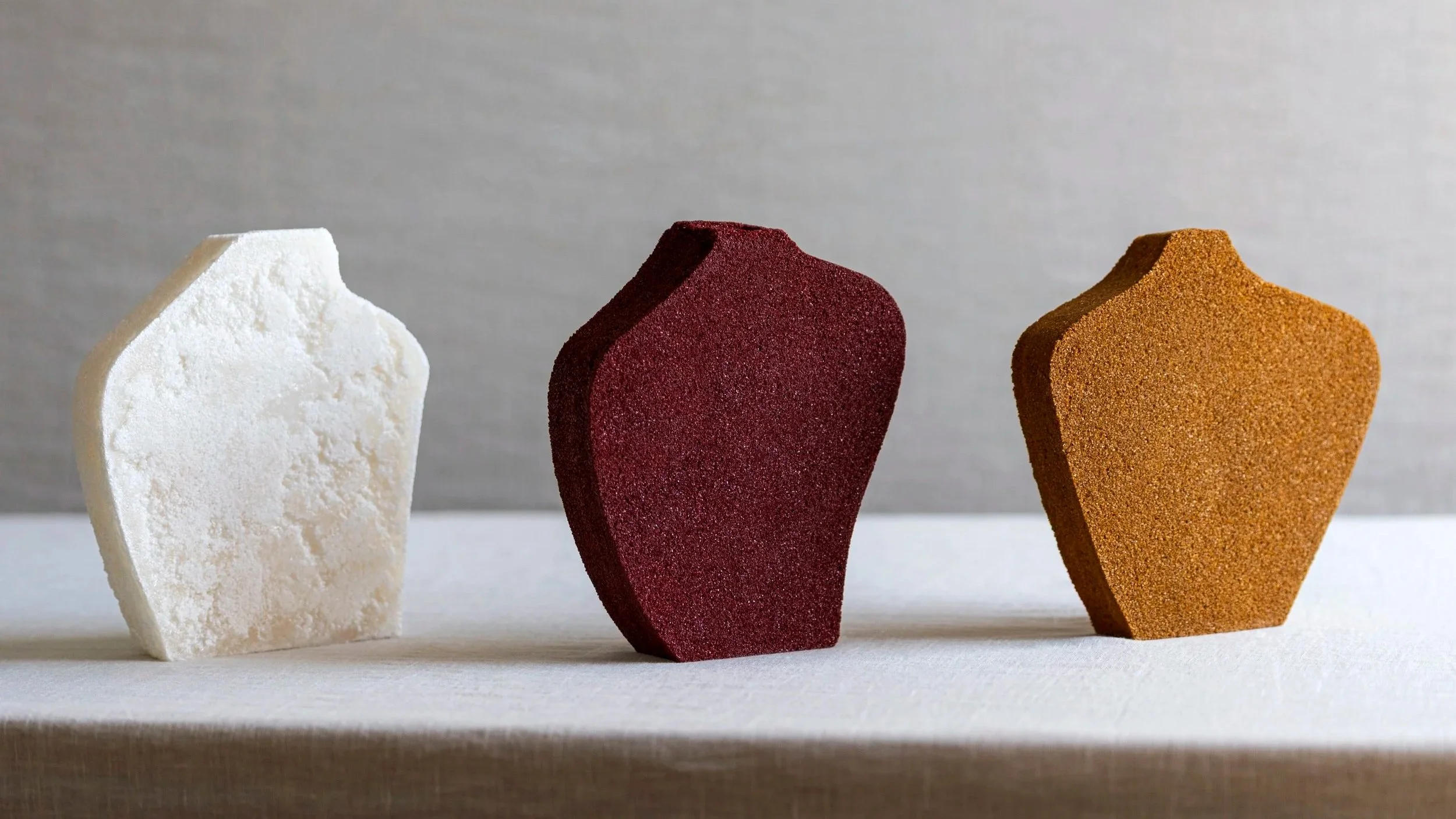
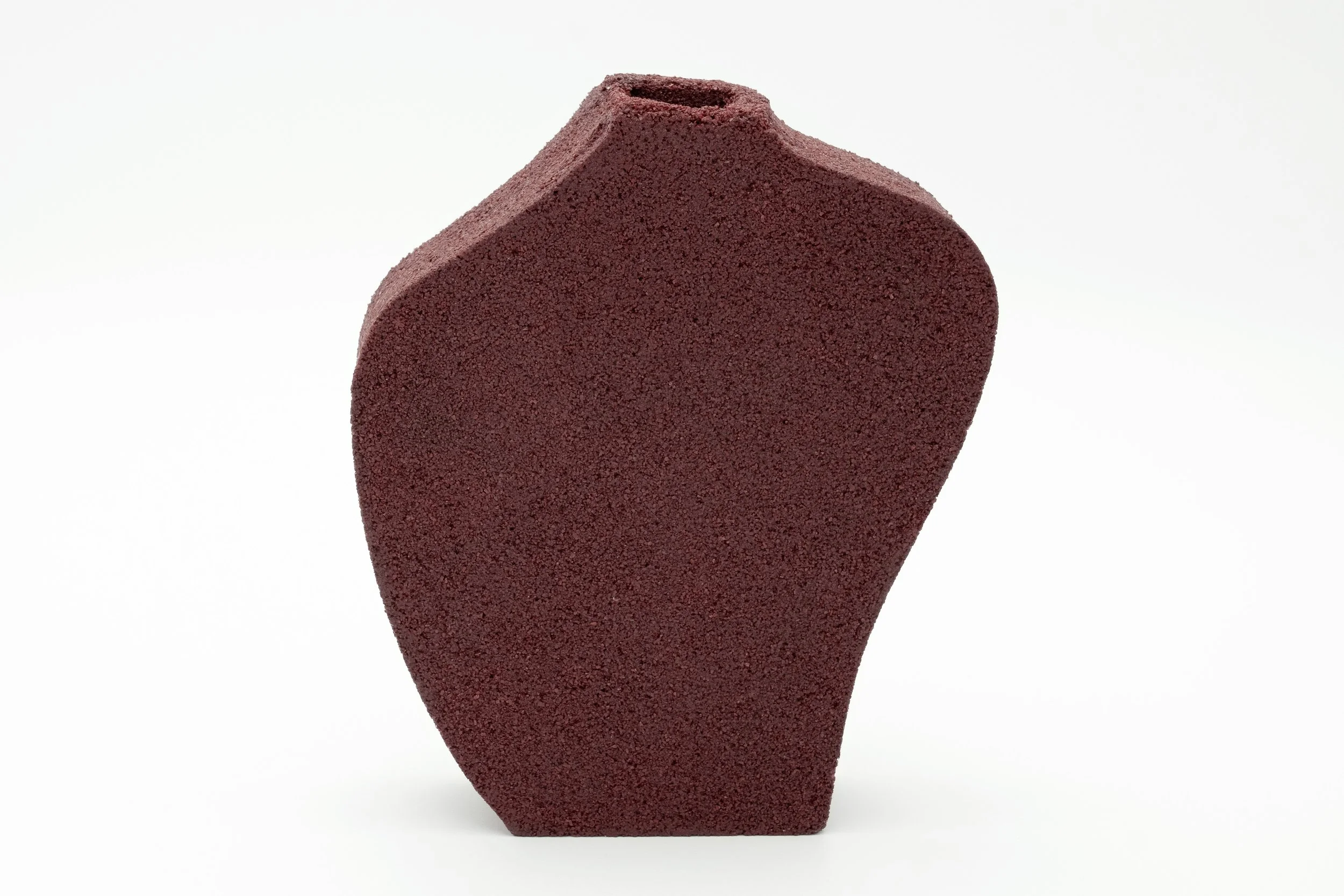
07 FINAL FORMS
A family of vessels produced from stabilized salt composites, demonstrating color variation, surface texture, and structural refinement.
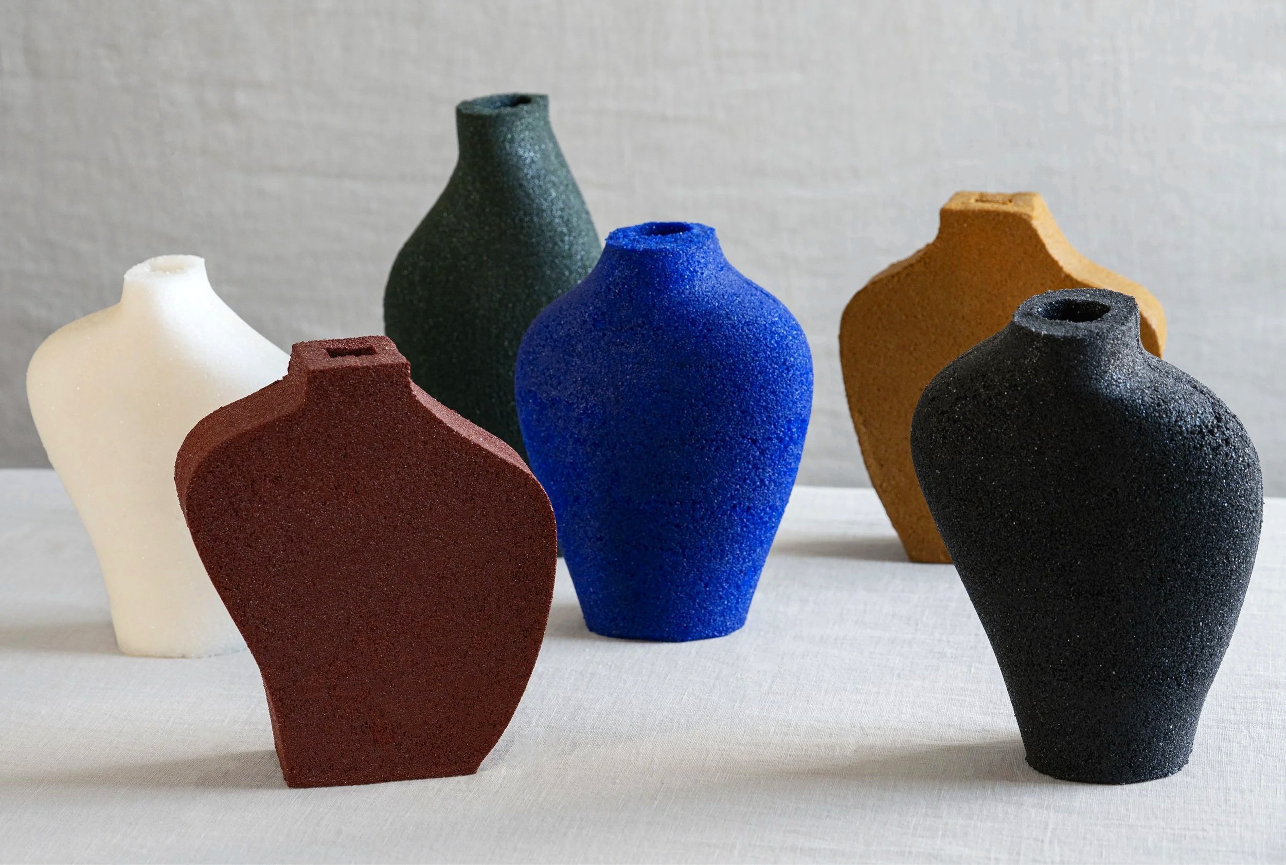
Vessel series
08 FABRICATION: LIGHTING DESIGN
Vertical Scaling Tests
To evaluate how the composite performs at architectural scale, tall cylindrical forms were cast at increasing height-to-diameter ratios. A layered application method, adapted from ceramic slip casting techniques, allowed controlled moisture release between coats and prevented structural failure in taller forms. These tests identified thresholds for wall thickness, curing orientation, and layer timing required to prevent cracking, collapse, and material sink. The results established parameters for maintaining translucency, structural cohesion, and surface uniformity in vertically scaled lighting components.

09 LIGHTING DESIGN
Final Forms
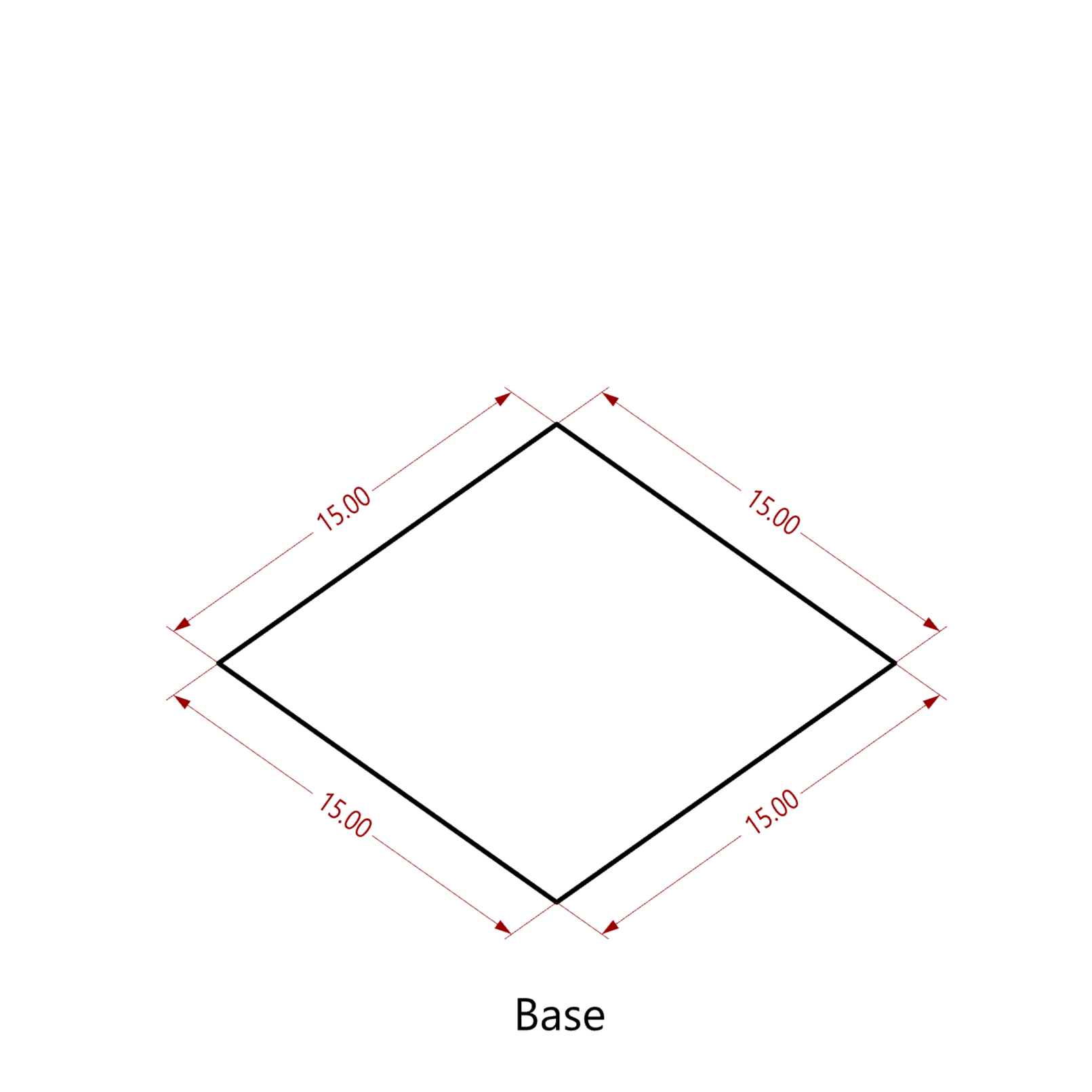
Parameters Diameter 15 cm, stable up to 1 m height Wall thickness 8 to 12 mm 3-5 pours per piece, overnight curing between layers
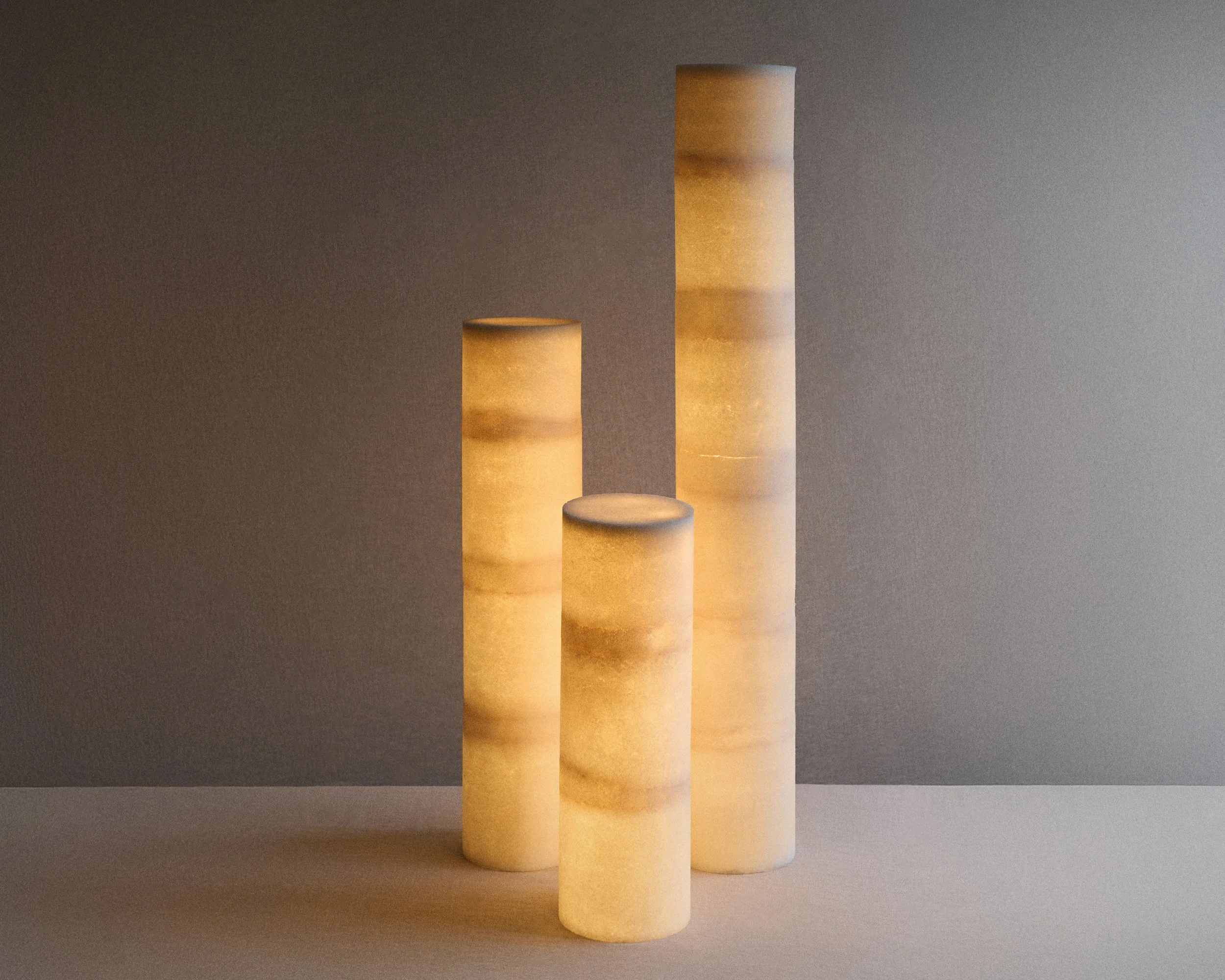
From left: 15x40, 15x70, 15x100cm